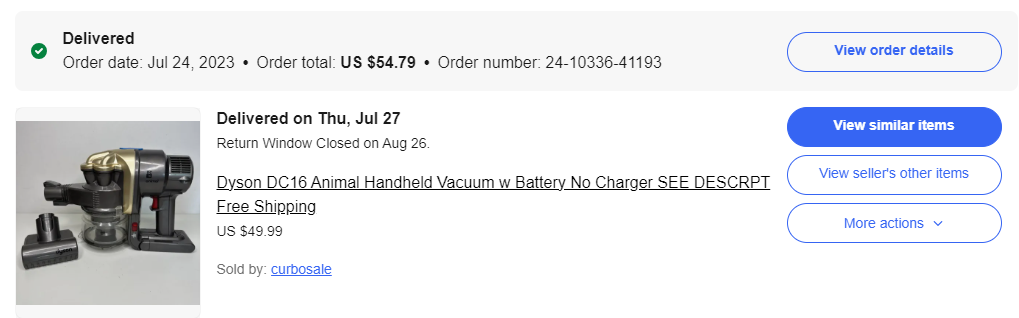
<?xml version="1.0" encoding="utf-8"?><feed xmlns="http://www.w3.org/2005/Atom" ><generator uri="https://jekyllrb.com/" version="3.10.0">Jekyll</generator><link href="https://ussery.info/feed.xml" rel="self" type="application/atom+xml" /><link href="https://ussery.info/" rel="alternate" type="text/html" /><updated>2026-06-24T12:35:52-07:00</updated><id>https://ussery.info/feed.xml</id><title type="html">Ussery.info</title><subtitle>Sporatic ramblings, teardowns, and the occasional nerdy project.</subtitle><author><name>Robert Ussery</name></author><entry><title type="html">Dyson Milwaukee Battery Adapter</title><link href="https://ussery.info/dyson-milwaukee-battery/" rel="alternate" type="text/html" title="Dyson Milwaukee Battery Adapter" /><published>2024-03-06T00:00:00-08:00</published><updated>2024-03-06T00:00:00-08:00</updated><id>https://ussery.info/dyson-milwaukee-battery</id><content type="html" xml:base="https://ussery.info/dyson-milwaukee-battery/"><![CDATA[<p>Recently I bought a (very) used Dyson DC16 handheld vacuum on Ebay for my office. I got a great deal on the vacuum because it came without a charger and needed some new seals and filters. I thought I would be able to use one of the other Dyson chargers we have kicking around the house, but alas it looks like nearly every Dyson line has a unique (if very similar looking) charger. In the case of the DC16, it annoyingly doesn’t have a DC barrel jack, but uses a charging cradle that interfaces to two contacts on the bottom of the vacuum.</p>

<figure class="">
  
  <img src="/assets/images/2024/ebay_listing.png" alt="" width="100%" />
  
  
</figure>

<p>I thought about buying a charger from Ebay or elsewhere, but they’re not super easy to come by and also end up costing nearly as much as I paid for the vacuum (which explains why I got such a good deal on the vacuum). I toyed around with 3D printing a new charge cradle, and even found <a href="https://www.printables.com/model/210126-dyson-dc16-charger">someone who had designed a cradle</a>. I printed this off, but found that it fit the vacuum very poorly and I struggled to find anything around my office to make into suitable charge contacts.</p>

<p>Additionally, the capacity of the battery was starting to reach end of life so it started to look like I should get a new battery as well. I hobbled along for a few months charging the vacuum from a bench power supply with leads clipped to the charge contacts, but I knew I would need to find a better approach.</p>

<h2 id="adapting-a-milwaukee-battery-to-the-dyson">Adapting a Milwaukee Battery to the Dyson</h2>

<p>At this point I decided the best approach would be to just replace the Dyson battery with a Milwaukee M18 battery since I already have a lot of those around my office for various power tools. This reduces the number of chargers I have cluttering the office as well as saves me buying a new battery and charger. I found several folks who had successfully done this using various power tool batteries:</p>
<ul>
  <li><a href="https://cults3d.com/en/3d-model/tool/adapter-milwaukee-m18-battery-to-dyson-dc16">VITOR_FR</a> has a 3D model for paid download on Cults3D</li>
  <li><a href="https://www.reddit.com/r/MilwaukeeTool/comments/lt7ojx/dyson_vacuum_with_milwaukee_battery_hack_your/">u/wuice</a> over on Reddit showed his solution using the husk of the old Dyson battery</li>
  <li><a href="https://www.printables.com/model/255397-dyson-dc16-to-dewalt-18v-battery">Yanev</a> has a 3D model on Printables for a Dewalt battery that looks exactly like what I’m after</li>
</ul>

<p>I didn’t want to pay for a 3D model and I wanted a cleaner solution than the hollowed-out Dyson battery, so I decided to go with something similar to what Yanev designed.</p>

<p>I departed from their design a bit by deciding to purchase an <a href="https://www.ebay.com/itm/143746077318">injection molded Milwaukee battery cradle</a> instead of 3D printing my own. I have a shop light that uses the Milwaukee batteries and has a 3D printed cradle and I find that the rough surface finish and imprecise tolerances cause the batteries to be tough to mate and de-mate from the light, so I figured going with an injection molded part would help smooth this out.</p>

<h2 id="vacuum-modifications">Vacuum Modifications</h2>
<p>I initially thought I would keep the vacuum cleaner un-modified and make this a purely drop-in replacement for the Dyson battery, but later decided against it. The Dyson battery has 6 cells vs. 5 cells for the Milwaukee battery, so I’d either need to integrate a boost converter on the 5 cell battery’s output or deal with only being able to use the Milwaukee battery when it is nearly fully charged before hitting the low voltage cutoff of the vacuum. Getting a boost converter that is reasonably small and cheap and can handle the full current draw of the vacuum (&gt;10A at full power) looked difficult, and the short battery life from using only the top range of the battery’s capacity would be annoying.</p>

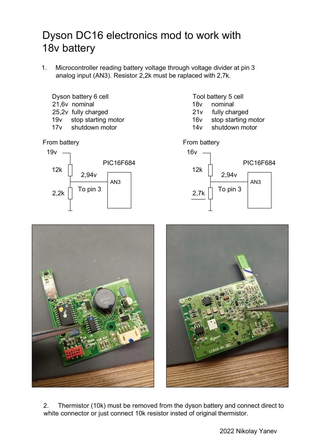
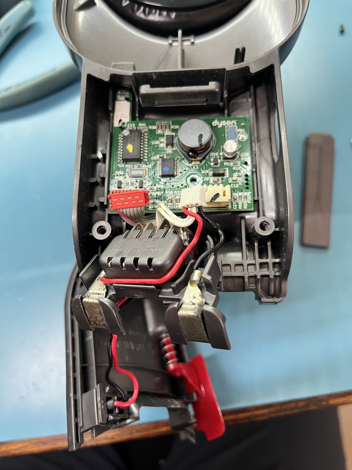
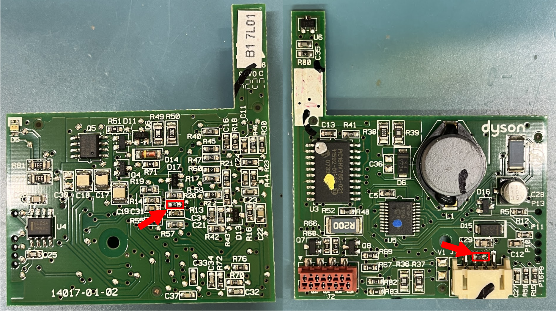
<p>Conveniently, our friend <a href="https://www.printables.com/model/255397-dyson-dc16-to-dewalt-18v-battery">Yanev</a> <a href="https://media.printables.com/media/prints/255397/images/2292488_1b502008-63d3-43e6-9a3a-69cc06b32f4c/thumbs/inside/1920x1440/jpg/dyson-dc16-electronics-mod-to-18v-1.webp">reverse engineered</a> the DC16’s control board and found the voltage divider used for measuring the battery voltage. Swapping a 2.7kΩ resistor in for the 2.2kΩ on the bottom of the divider gives us a 14V cutoff voltage which gives a healthy 2.8V/cell cutoff for the Milwaukee battery. Pulling the control board was pretty easy:</p>
<figure class="">
  <a href="/assets/images/2024/Dyson%20Teardown.JPG">
  <img src="/assets/images/2024/Dyson%20Teardown.JPG" alt="" width="30%" />
  </a>
  
</figure>

<p>And then swapping R13 on the bottom of the board to a 2.7kΩ 0603 resistor was also super easy. While I was in there, I also soldered a 10kΩ resistor across the pins of the connector that previously connected to the Dyson battery’s 10k NTC thermistor. In the future I’d like to actually wire in the Milwaukee battery’s thermistor, but the injection molded cradle I bought doesn’t include the thermistor contacts so for now I’m just disabling the thermal cutoff features with this resistor.</p>
<figure class="">
  <a href="/assets/images/2024/Reworks.png">
  <img src="/assets/images/2024/Reworks.png" alt="" width="50%" />
  </a>
  
</figure>

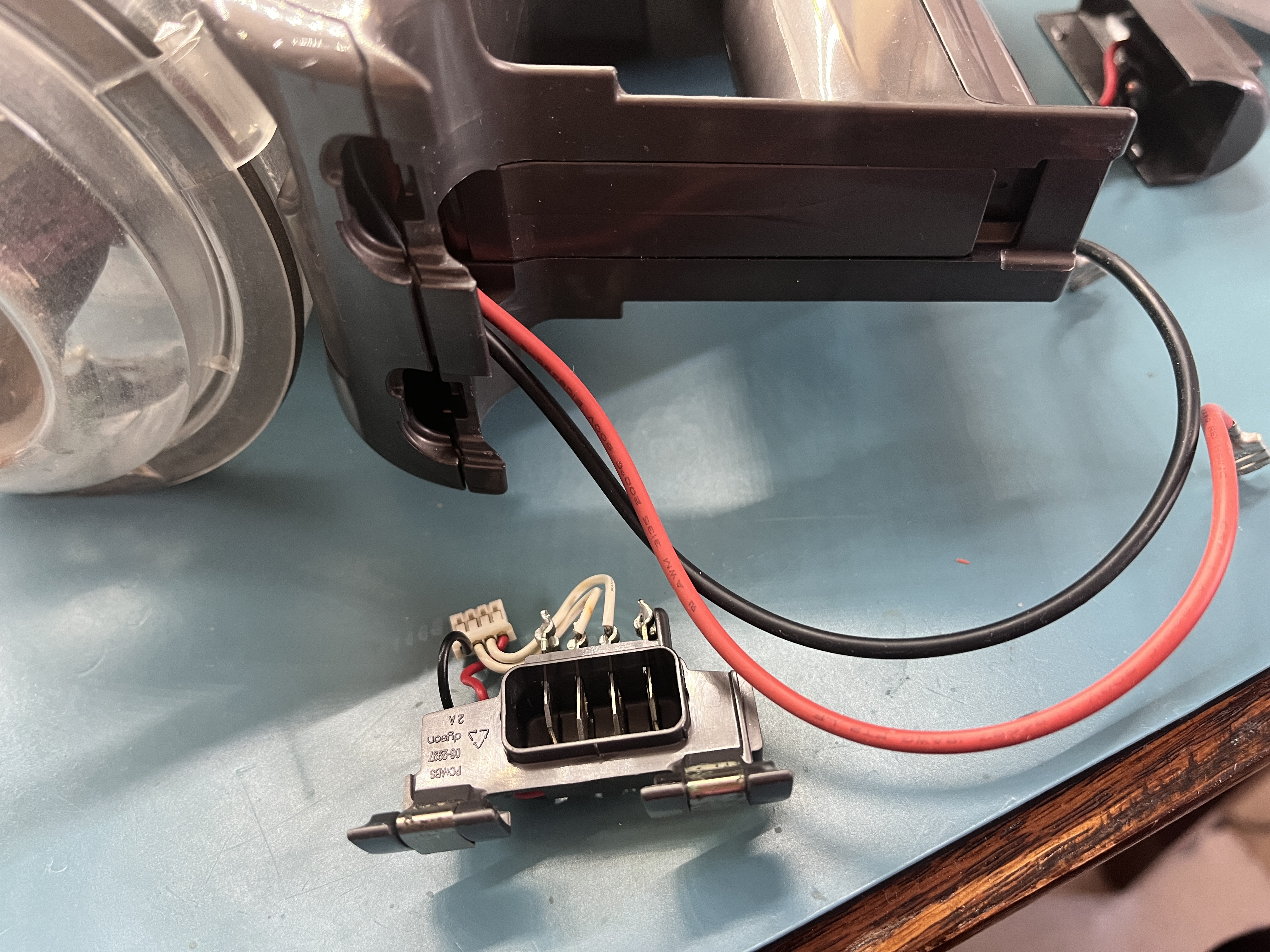
<p>I removed the charge and battery contact assembly from the vacuum, which gives me a clear aperture to pass the power wires through, and also allows the 3D printed adapter to be more rigidly attached to the vacuum. I de-soldered the two power leads from the battery contact assembly, being very careful not to overheat the plastic and damage the assembly. I then extended the battery wires with a bit of 16AWG high-flex wire.</p>
<figure class="">
  <a href="/assets/images/2024/Vacuum%20without%20battery%20contacts.JPG">
  <img src="/assets/images/2024/Vacuum%20without%20battery%20contacts.JPG" alt="" width="50%" />
  </a>
  
</figure>

<p>All of these modifications to the vacuum are easily reversible (reinstall the battery contact assembly, swap R13 back to its original value, remove the thermistor mockup resistor), so this whole adventure is low risk to the health and value of the vacuum.</p>

<h2 id="3d-printed-adapter">3D Printed Adapter</h2>
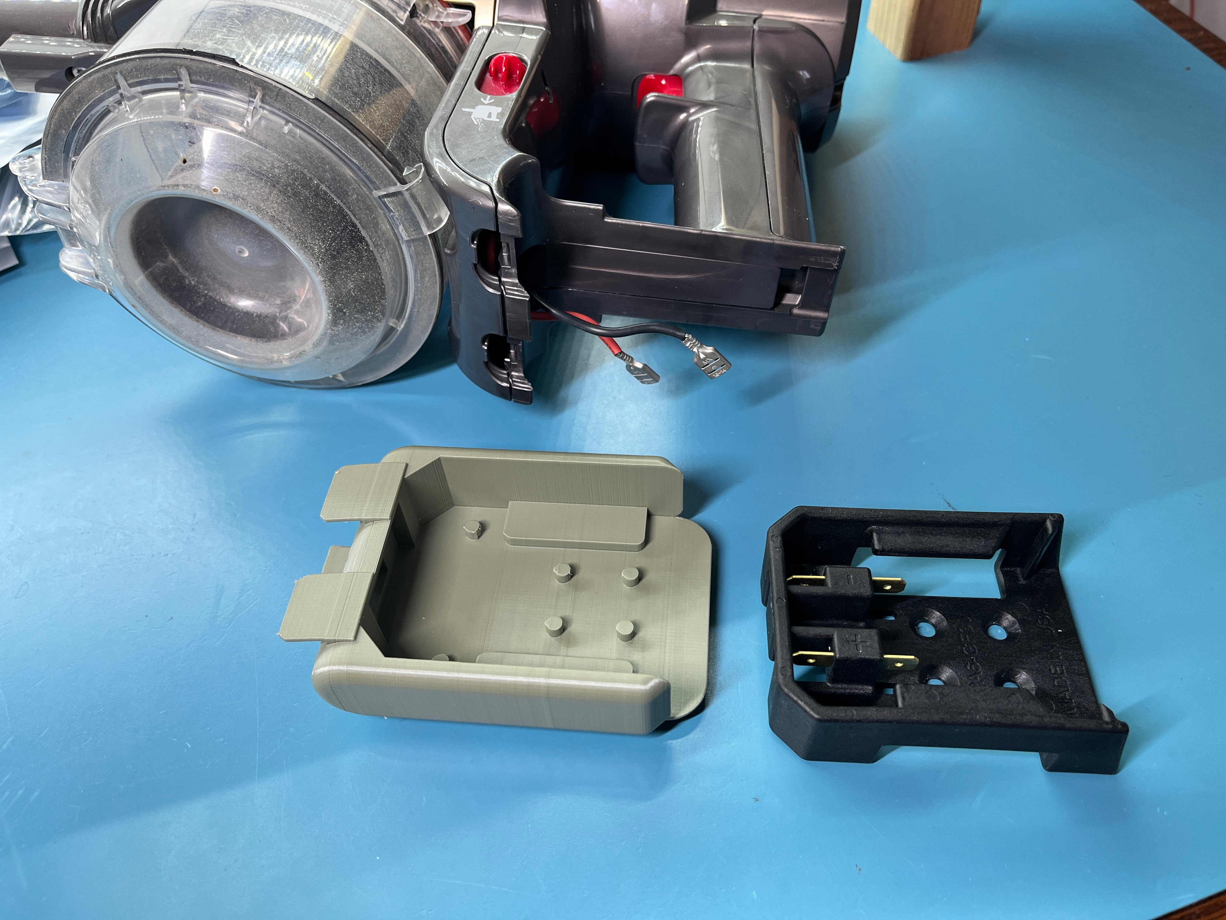
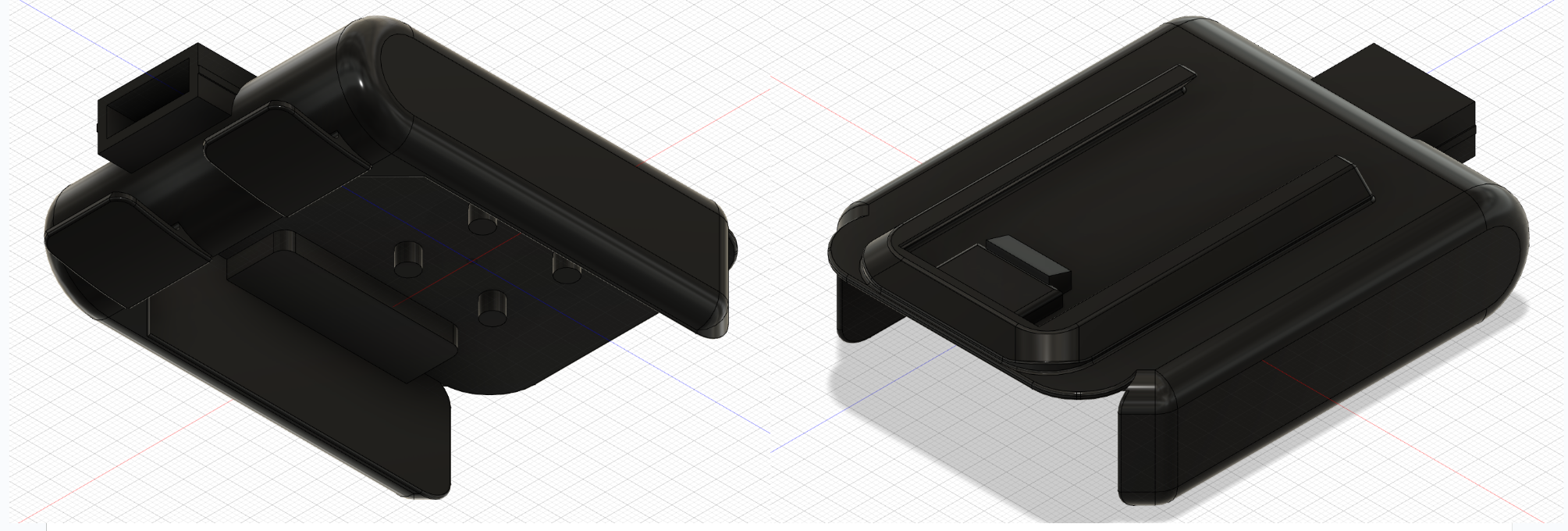
<p>I whipped up a 3D printed part to adapt the Milwaukee battery cradle to the dovetail battery slide on the bottom of the Dyson. I wanted to keep the 3D printed part as short as possible in the vertical dimension, so I didn’t want to use screws to attach the 3D printed part to the battery cradle. Instead, I included some 4mm tall posts in the 3D printed part that pass through the six screw holes in the battery cradle. Once assembled, I melted the posts down with a soldering iron to rivet the two parts together.</p>
<figure class="">
  <a href="/assets/images/2024/3D%20printed%20adapter%20CAD.png">
  <img src="/assets/images/2024/3D%20printed%20adapter%20CAD.png" alt="" width="50%" />
  </a>
  
</figure>
<figure class="">
  <a href="/assets/images/2024/vacuum_parts.JPG">
  <img src="/assets/images/2024/vacuum_parts.JPG" alt="" width="50%" />
  </a>
  
</figure>

<h2 id="the-finished-product">The Finished Product</h2>
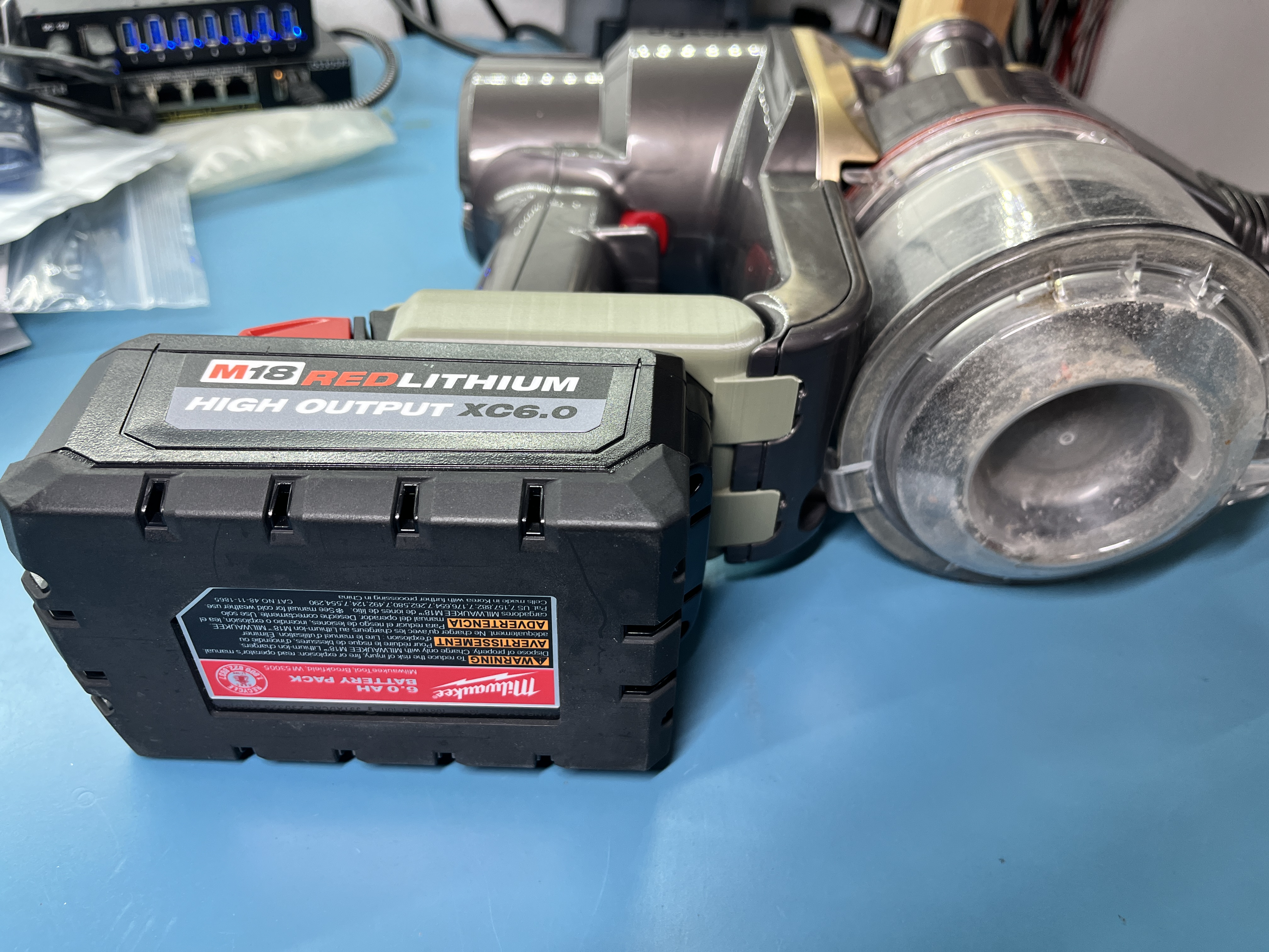
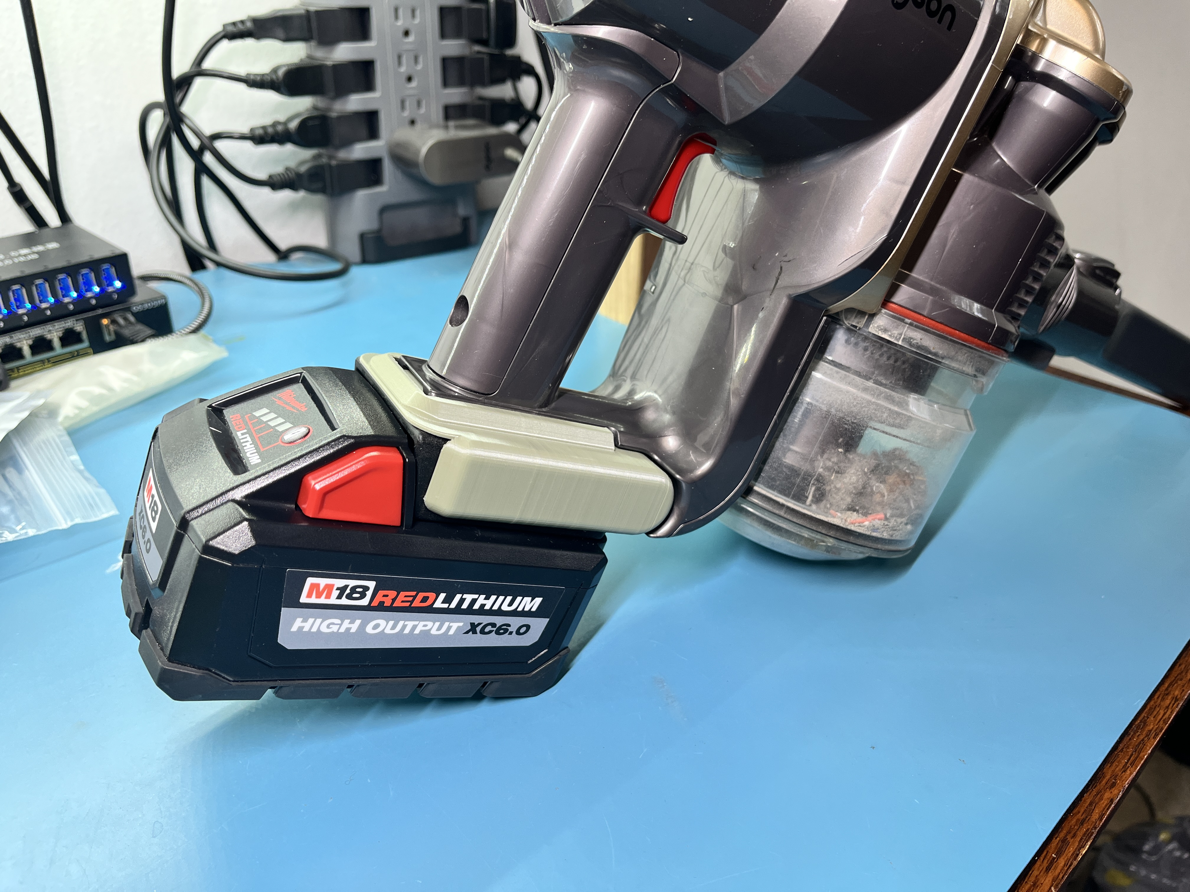
<p>I’m extremely pleased with how well this modification worked. The vacuum cleaner runs great and has plenty of power even running on the lower voltage 5 cell battery. It is a bit heavier with the Milwaukee battery (particularly if I use one of the larger XC6.0 high capacity batteries), but it remains well balanced and feels great to use.</p>
<figure class="">
  <a href="/assets/images/2024/vacuum_bottom.JPG">
  <img src="/assets/images/2024/vacuum_bottom.JPG" alt="" width="50%" />
  </a>
  
</figure>

<p>The Milwaukee battery is very easy to install and remove, and feels very securely attached to the vacuum. I was concerned that it would be a bit loosey goosey since it is a lot heavier than the Dyson battery, but I managed to get the 3D printed adapter dimensions all to the point where it is a pretty rigid assembly.</p>

<p>One minor annoyance is that the vacuum now doesn’t sit well on a flat surface. I had contemplated flipping the orientation of the battery so that it sits more under the body of the vacuum, but then the 3D printed adapter would have had to be around 25mm taller to allow the battery to slide on and off. I think I like this implementation better, even if it causes the vacuum to sit at a goofy angle.</p>

<figure class="">
  <a href="/assets/images/2024/vacuum_side.JPG">
  <img src="/assets/images/2024/vacuum_side.JPG" alt="" width="100%" />
  </a>
  
</figure>

<p>If you want to do this yourself, just follow this set of steps:</p>
<ol>
  <li>Buy one of the injection molded M18 battery cradles (Ebay link)</li>
  <li>Print the battery adapter (on <a href="https://www.printables.com/model/796334-dyson-dc16-milwaukee-m18-battery-adapter">Printables</a> or Github <a href="/assets/files/Dyson DC16 Milwaukee Battery Adapter v4.step">.step</a> <a href="/assets/files/Dyson DC16 Milwaukee Battery Adapter v4.stl">.stl</a>)</li>
  <li>Tear down your vacuum, remove the battery contact assembly, extend the battery power wires, and terminate with 6.3mm spade terminals</li>
  <li>Modify the vacuum controller board, swapping R13 for a 2.7kΩ 0603 resistor, and adding a 10kΩ resistor across the terminals of the battery thermistor input</li>
  <li>Reassemble the vacuum, assemble the battery cradle to the 3D printed adapter, plug in the power wires</li>
  <li>Bask in the beauty of a Milwaukee-powered Dyson!</li>
</ol>]]></content><author><name>Robert Ussery</name></author><category term="3D Printing" /><category term="vacuum cleaner" /><category term="hacks" /><summary type="html"><![CDATA[Recently I bought a (very) used Dyson DC16 handheld vacuum on Ebay for my office. I got a great deal on the vacuum because it came without a charger and needed some new seals and filters. I thought I would be able to use one of the other Dyson chargers we have kicking around the house, but alas it looks like nearly every Dyson line has a unique (if very similar looking) charger. In the case of the DC16, it annoyingly doesn’t have a DC barrel jack, but uses a charging cradle that interfaces to two contacts on the bottom of the vacuum. I thought about buying a charger from Ebay or elsewhere, but they’re not super easy to come by and also end up costing nearly as much as I paid for the vacuum (which explains why I got such a good deal on the vacuum). I toyed around with 3D printing a new charge cradle, and even found someone who had designed a cradle. I printed this off, but found that it fit the vacuum very poorly and I struggled to find anything around my office to make into suitable charge contacts. Additionally, the capacity of the battery was starting to reach end of life so it started to look like I should get a new battery as well. I hobbled along for a few months charging the vacuum from a bench power supply with leads clipped to the charge contacts, but I knew I would need to find a better approach. Adapting a Milwaukee Battery to the Dyson At this point I decided the best approach would be to just replace the Dyson battery with a Milwaukee M18 battery since I already have a lot of those around my office for various power tools. This reduces the number of chargers I have cluttering the office as well as saves me buying a new battery and charger. I found several folks who had successfully done this using various power tool batteries: VITOR_FR has a 3D model for paid download on Cults3D u/wuice over on Reddit showed his solution using the husk of the old Dyson battery Yanev has a 3D model on Printables for a Dewalt battery that looks exactly like what I’m after I didn’t want to pay for a 3D model and I wanted a cleaner solution than the hollowed-out Dyson battery, so I decided to go with something similar to what Yanev designed. I departed from their design a bit by deciding to purchase an injection molded Milwaukee battery cradle instead of 3D printing my own. I have a shop light that uses the Milwaukee batteries and has a 3D printed cradle and I find that the rough surface finish and imprecise tolerances cause the batteries to be tough to mate and de-mate from the light, so I figured going with an injection molded part would help smooth this out. Vacuum Modifications I initially thought I would keep the vacuum cleaner un-modified and make this a purely drop-in replacement for the Dyson battery, but later decided against it. The Dyson battery has 6 cells vs. 5 cells for the Milwaukee battery, so I’d either need to integrate a boost converter on the 5 cell battery’s output or deal with only being able to use the Milwaukee battery when it is nearly fully charged before hitting the low voltage cutoff of the vacuum. Getting a boost converter that is reasonably small and cheap and can handle the full current draw of the vacuum (&gt;10A at full power) looked difficult, and the short battery life from using only the top range of the battery’s capacity would be annoying. Conveniently, our friend Yanev reverse engineered the DC16’s control board and found the voltage divider used for measuring the battery voltage. Swapping a 2.7kΩ resistor in for the 2.2kΩ on the bottom of the divider gives us a 14V cutoff voltage which gives a healthy 2.8V/cell cutoff for the Milwaukee battery. Pulling the control board was pretty easy: And then swapping R13 on the bottom of the board to a 2.7kΩ 0603 resistor was also super easy. While I was in there, I also soldered a 10kΩ resistor across the pins of the connector that previously connected to the Dyson battery’s 10k NTC thermistor. In the future I’d like to actually wire in the Milwaukee battery’s thermistor, but the injection molded cradle I bought doesn’t include the thermistor contacts so for now I’m just disabling the thermal cutoff features with this resistor. I removed the charge and battery contact assembly from the vacuum, which gives me a clear aperture to pass the power wires through, and also allows the 3D printed adapter to be more rigidly attached to the vacuum. I de-soldered the two power leads from the battery contact assembly, being very careful not to overheat the plastic and damage the assembly. I then extended the battery wires with a bit of 16AWG high-flex wire. All of these modifications to the vacuum are easily reversible (reinstall the battery contact assembly, swap R13 back to its original value, remove the thermistor mockup resistor), so this whole adventure is low risk to the health and value of the vacuum. 3D Printed Adapter I whipped up a 3D printed part to adapt the Milwaukee battery cradle to the dovetail battery slide on the bottom of the Dyson. I wanted to keep the 3D printed part as short as possible in the vertical dimension, so I didn’t want to use screws to attach the 3D printed part to the battery cradle. Instead, I included some 4mm tall posts in the 3D printed part that pass through the six screw holes in the battery cradle. Once assembled, I melted the posts down with a soldering iron to rivet the two parts together. The Finished Product I’m extremely pleased with how well this modification worked. The vacuum cleaner runs great and has plenty of power even running on the lower voltage 5 cell battery. It is a bit heavier with the Milwaukee battery (particularly if I use one of the larger XC6.0 high capacity batteries), but it remains well balanced and feels great to use. The Milwaukee battery is very easy to install and remove, and feels very securely attached to the vacuum. I was concerned that it would be a bit loosey goosey since it is a lot heavier than the Dyson battery, but I managed to get the 3D printed adapter dimensions all to the point where it is a pretty rigid assembly. One minor annoyance is that the vacuum now doesn’t sit well on a flat surface. I had contemplated flipping the orientation of the battery so that it sits more under the body of the vacuum, but then the 3D printed adapter would have had to be around 25mm taller to allow the battery to slide on and off. I think I like this implementation better, even if it causes the vacuum to sit at a goofy angle. If you want to do this yourself, just follow this set of steps: Buy one of the injection molded M18 battery cradles (Ebay link) Print the battery adapter (on Printables or Github .step .stl) Tear down your vacuum, remove the battery contact assembly, extend the battery power wires, and terminate with 6.3mm spade terminals Modify the vacuum controller board, swapping R13 for a 2.7kΩ 0603 resistor, and adding a 10kΩ resistor across the terminals of the battery thermistor input Reassemble the vacuum, assemble the battery cradle to the 3D printed adapter, plug in the power wires Bask in the beauty of a Milwaukee-powered Dyson!]]></summary></entry><entry><title type="html">DIY Webcam Enclosure</title><link href="https://ussery.info/camera-enclosure/" rel="alternate" type="text/html" title="DIY Webcam Enclosure" /><published>2020-10-25T00:00:00-07:00</published><updated>2020-10-25T00:00:00-07:00</updated><id>https://ussery.info/camera-enclosure</id><content type="html" xml:base="https://ussery.info/camera-enclosure/"><![CDATA[<p>As with many folks over the last year, I’ve been working from home since the start of the COVID pandemic. I unfortunately didn’t have a webcam back in March for the new world of Zoom meetings, so I hopped on Amazon to find one. Finding one that was in stock at that time and not outrageously expensive was more difficult than I had anticipated and I ended up buying a bare-board USB camera: <a href="https://www.amazon.com/gp/product/B00SPBWM0M/">ELP 2.8-12mm Varifocal Lens Camera</a>.</p>
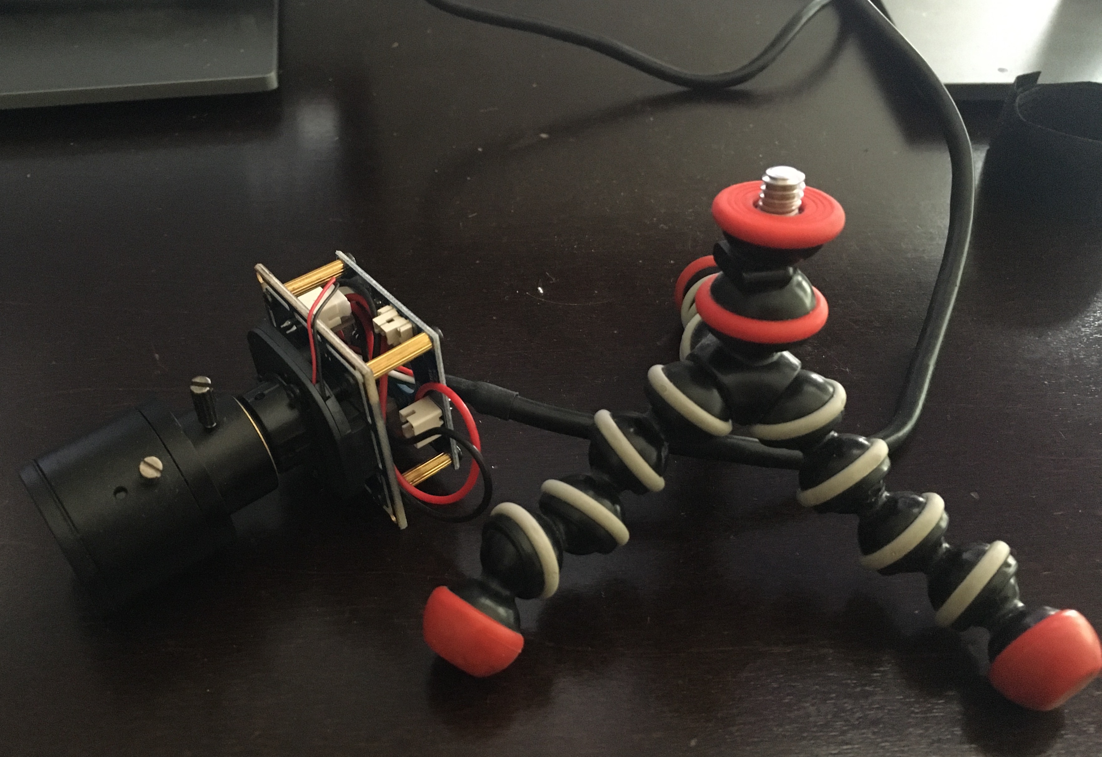
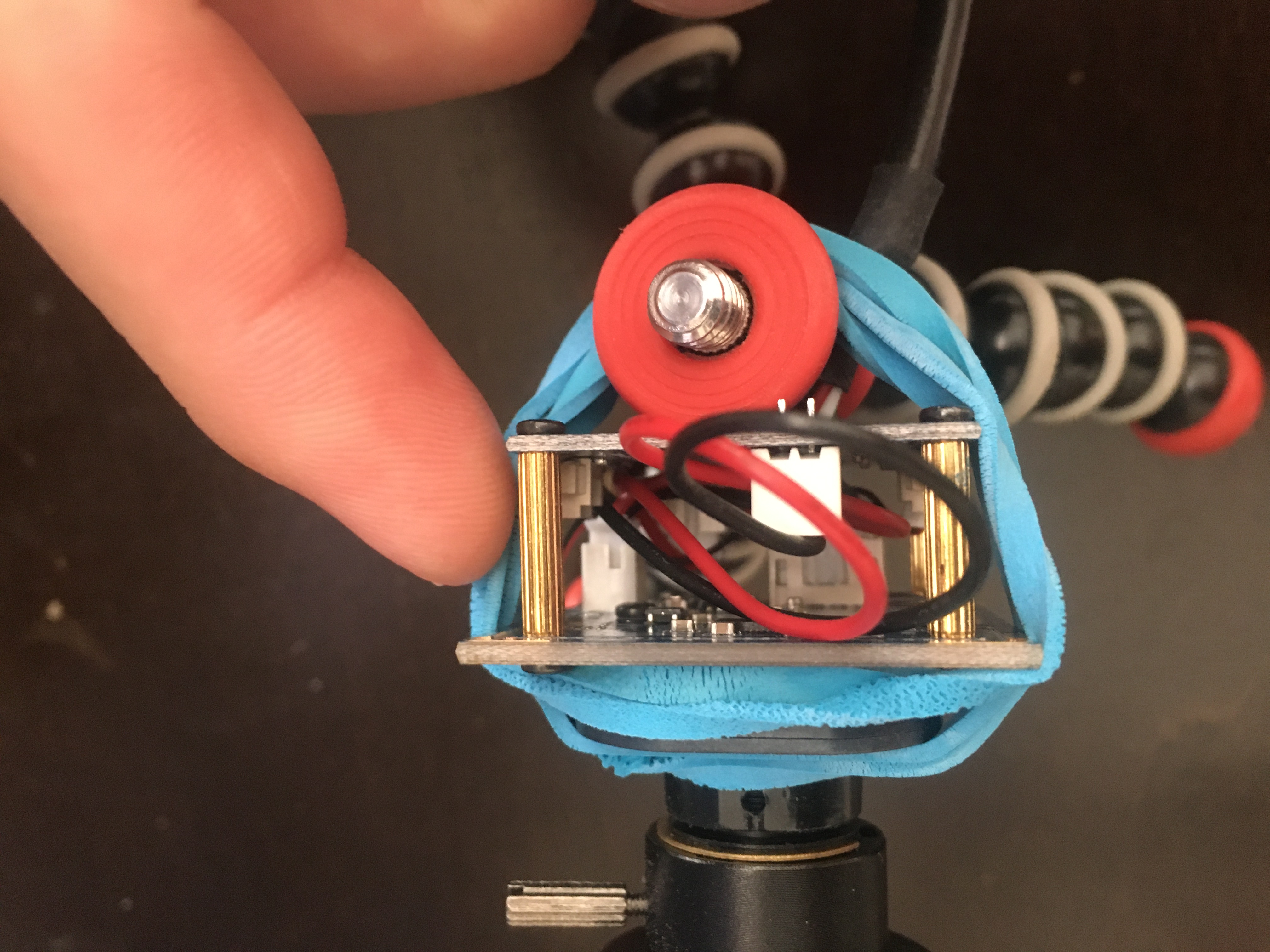
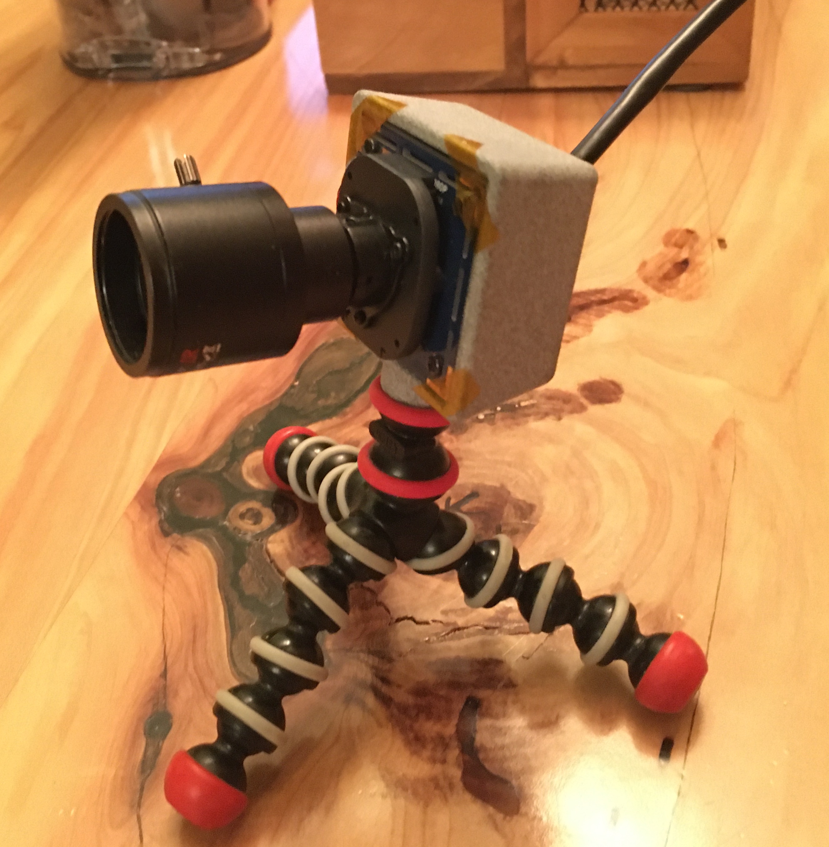
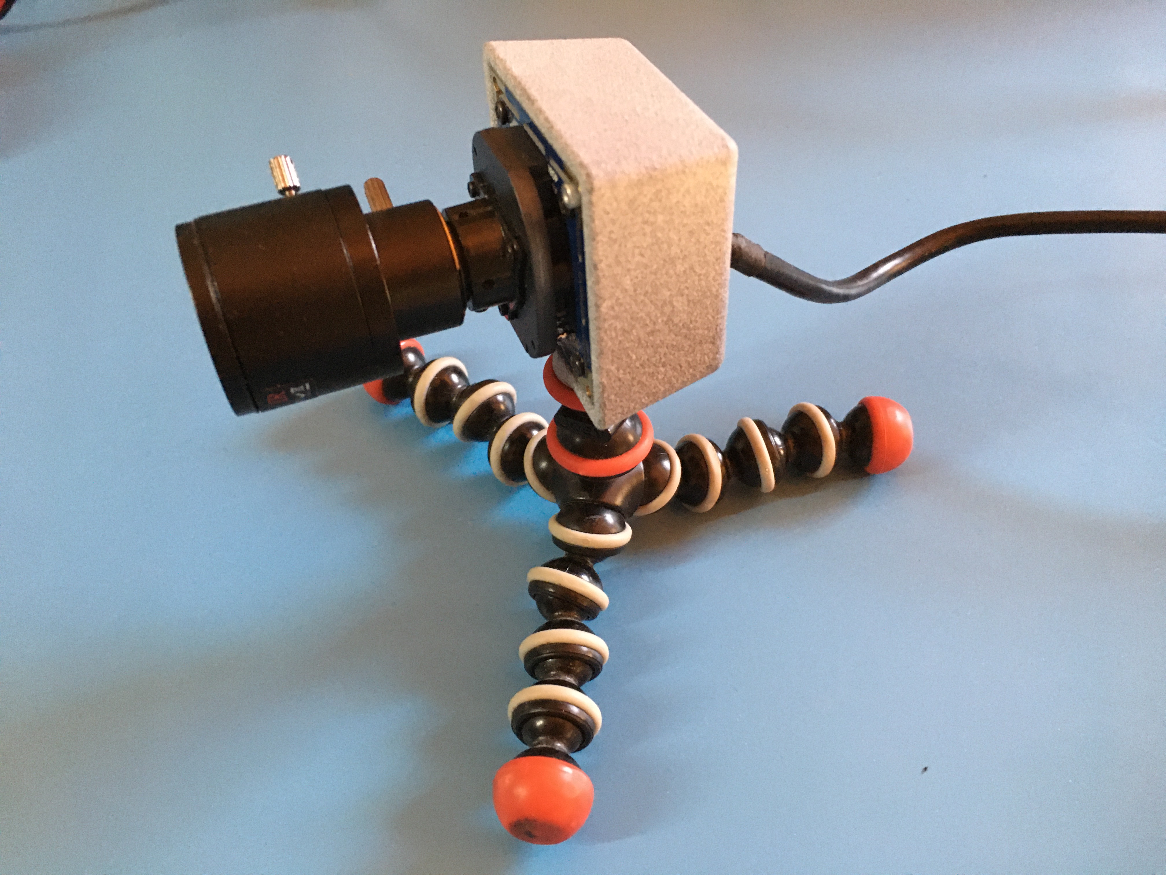
<p>This camera doesn’t have an enclosure or any way to hold it in position. I ended up using some rubber bands to hold it to a miniature Joby tripod that I had hanging around:</p>

<p><a href="/assets/images/2020/webcam_with_tripod.jpg"><img src="/assets/images/2020/webcam_with_tripod.jpg" alt="Camera and Tripod" width="50%" /></a>
<a href="/assets/images/2020/rubber_bands.jpg"><img src="/assets/images/2020/rubber_bands.jpg" alt="Rubber Bands" width="25%" /></a>
<!--more--></p>

<h2 id="the-design">The Design</h2>

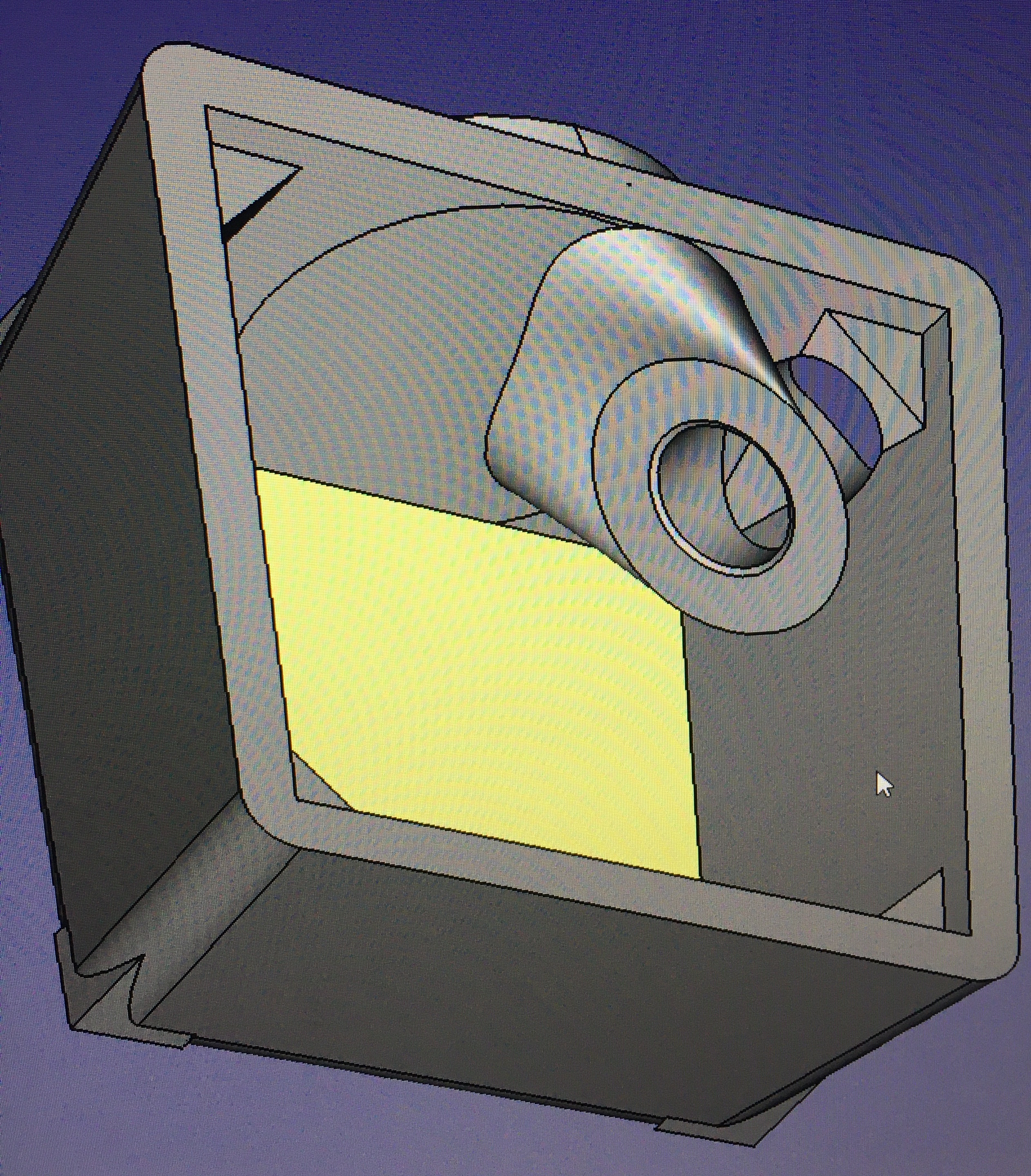
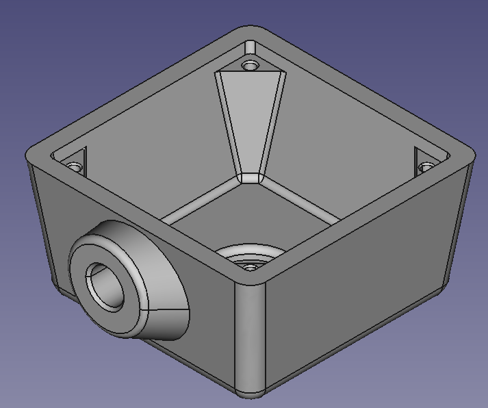
<p>As you can see in the photos, this solution was left much to be desired in terms of long-term durability. I decided to give 3D printing an enclosure a shot and whipped up a quick solution in FreeCAD. Demonstrating my lack of CAD skills, I managed to end up with this masterpiece:</p>

<p><a href="/assets/images/2020/how_does_cad_work.jpg"><img src="/assets/images/2020/how_does_cad_work.jpg" alt="Weird Science" width="50%" /></a></p>

<p>I managed to get it sorted out and into something a bit more reasonable, after thirty minutes and a bit of cursing:
<a href="/assets/images/2020/case_iso.png"><img src="/assets/images/2020/case_iso.png" alt="Enclosure CAD" width="50%" /></a></p>

<p>I had planned on using a brass threaded insert for the tripod attachment on the bottom and using threadforming M2 screws into the small holes in the camera mounting bosses.</p>

<p>My friend John who works for a high-end 3D printing and prototyping company offered to print the case for me. He got the design into a bulk print of <a href="https://www.fastradius.com/resources/polyamide-12/">PA12</a> that his company had running, and even said he could print the tripod threads into the design instead of adding a threaded insert after the fact. Unfortunately the M2 screw holes were too small to print, so those got scrapped on the final design.</p>

<h2 id="the-goods">The Goods</h2>

<p>Fast forward to a few days later - I got the finished parts back and gave it a test fit:</p>

<p><a href="/assets/images/2020/enclosure_glamor_shot.jpg"><img src="/assets/images/2020/enclosure_glamor_shot.jpg" alt="Enclosure First Fit Check" width="50%" /></a></p>

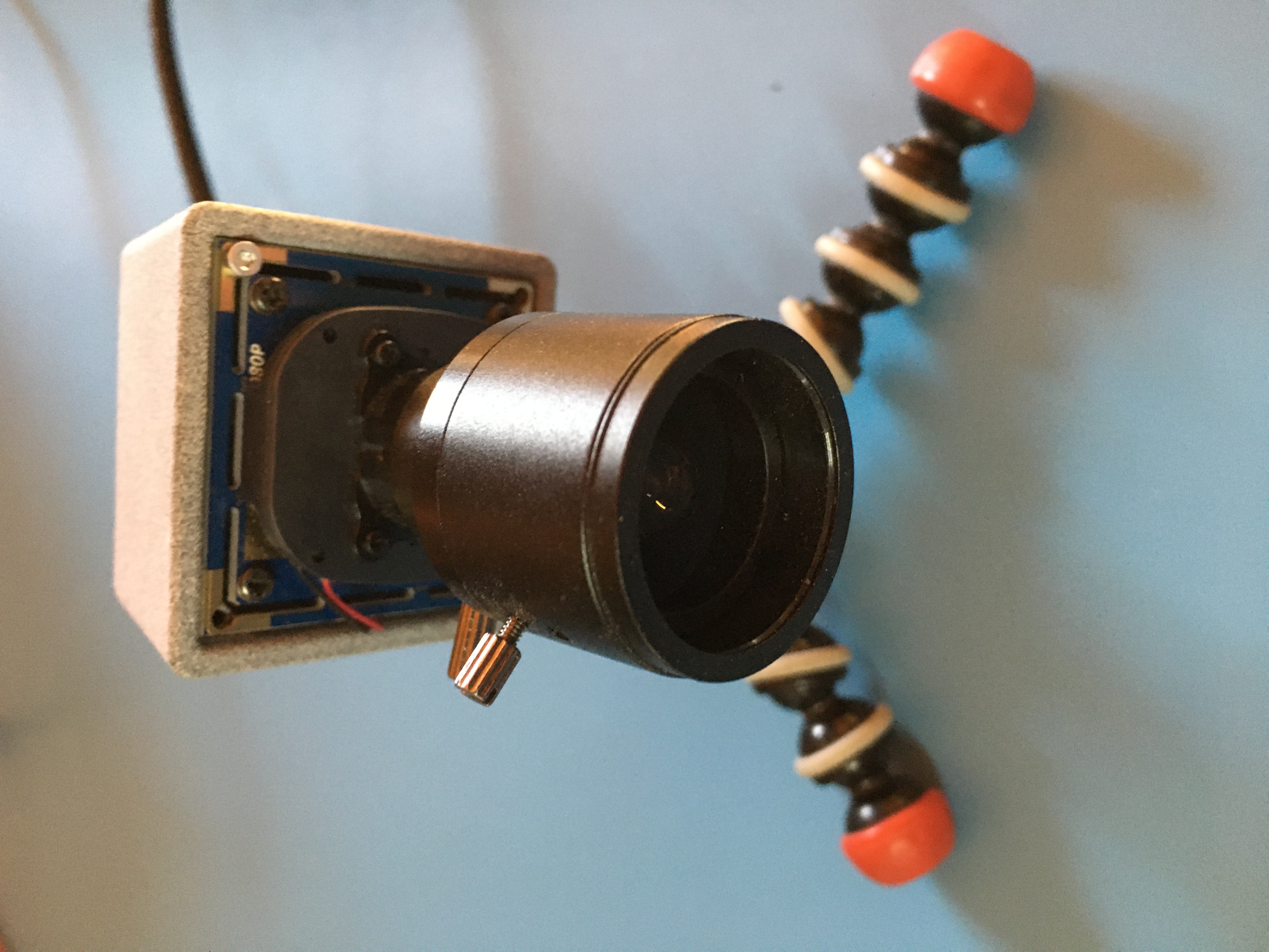
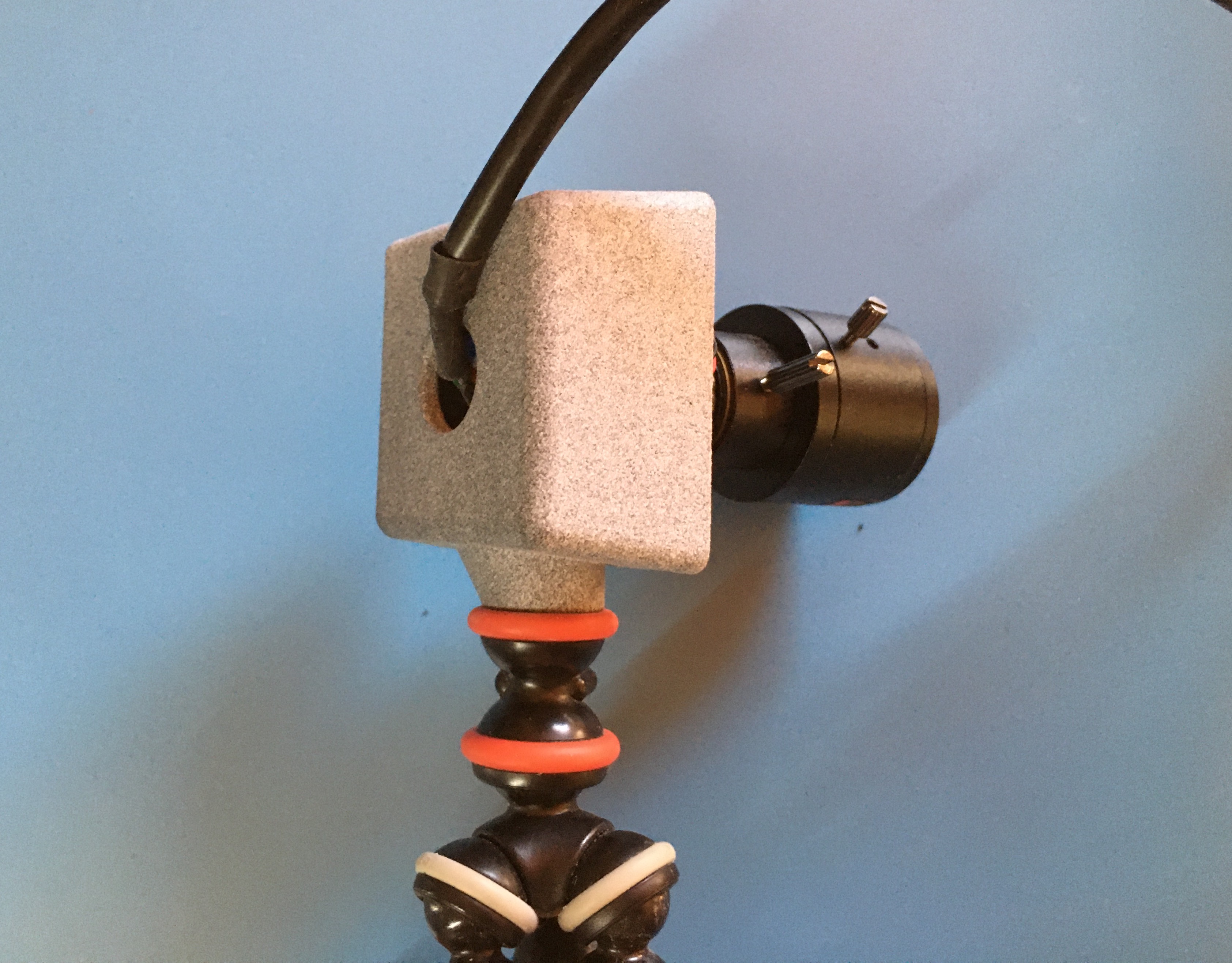
<p>Woohoo! It was a perfect fit. Here are a few more shots, with the #2 screws drilled and tapped in place to hold the camera instead of the kapton tape I’d used on the fit-check:
<a href="/assets/images/2020/front_view.jpg"><img src="/assets/images/2020/front_view.jpg" alt="Front View" width="50%" /></a>
<a href="/assets/images/2020/rear_view.jpg"><img src="/assets/images/2020/rear_view.jpg" alt="Rear View" width="50%" /></a>
<a href="/assets/images/2020/side_angle_view.jpg"><img src="/assets/images/2020/side_angle_view.jpg" alt="Iso View" width="50%" /></a></p>

<h2 id="design-files">Design Files</h2>

<p>Here’s the design if you’d like to use it for this camera:<br />
<a href="/assets/files/camera_case.FCStd">camera_case.FCStd (1.1MB FreeCAD)</a><br />
<a href="/assets/files/camera_case.step">camera_case.step (1.2MB Step file)</a></p>

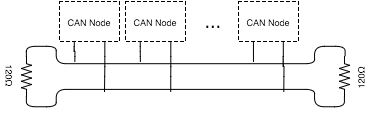
<p>Note that these files don’t include the tripod threads and still have the M2 screw holes that weren’t present in the final print.</p>]]></content><author><name>Robert Ussery</name></author><category term="3D Printing" /><category term="webcam" /><category term="COVID" /><summary type="html"><![CDATA[As with many folks over the last year, I’ve been working from home since the start of the COVID pandemic. I unfortunately didn’t have a webcam back in March for the new world of Zoom meetings, so I hopped on Amazon to find one. Finding one that was in stock at that time and not outrageously expensive was more difficult than I had anticipated and I ended up buying a bare-board USB camera: ELP 2.8-12mm Varifocal Lens Camera. This camera doesn’t have an enclosure or any way to hold it in position. I ended up using some rubber bands to hold it to a miniature Joby tripod that I had hanging around:]]></summary></entry><entry><title type="html">CAN Bus Bridge</title><link href="https://ussery.info/can-bridge/" rel="alternate" type="text/html" title="CAN Bus Bridge" /><published>2015-12-30T00:00:00-08:00</published><updated>2015-12-30T00:00:00-08:00</updated><id>https://ussery.info/can-bridge</id><content type="html" xml:base="https://ussery.info/can-bridge/"><![CDATA[<p>This project grew out of a problem we were running into at <a href="https://www.airware.com">Airware</a>. The physical layout of some of the aircraft we were putting our autopilot hardware onto made it difficult to properly terminate our CAN buses at each end. In a normal CAN bus, there all of the nodes are connected on a single bus, which is terminated by a 120Ω resistor at each end.
<img src="/assets/images/old_posts/can_bus_diagram.png" alt="CAN Bus Diagram" /></p>

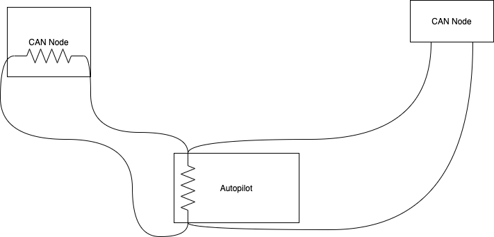
<p>The autopilot we had designed had onboard termination for one end of the CAN bus, and then the other end would be terminated at one of the nodes on the bus. This made it difficult to terminate the bus correctly if the autopilot was not physically located at one end of the bus:
<img src="/assets/images/old_posts/autopilot_can.png" alt="Autopilot CAN Bus" />
<!--more--></p>

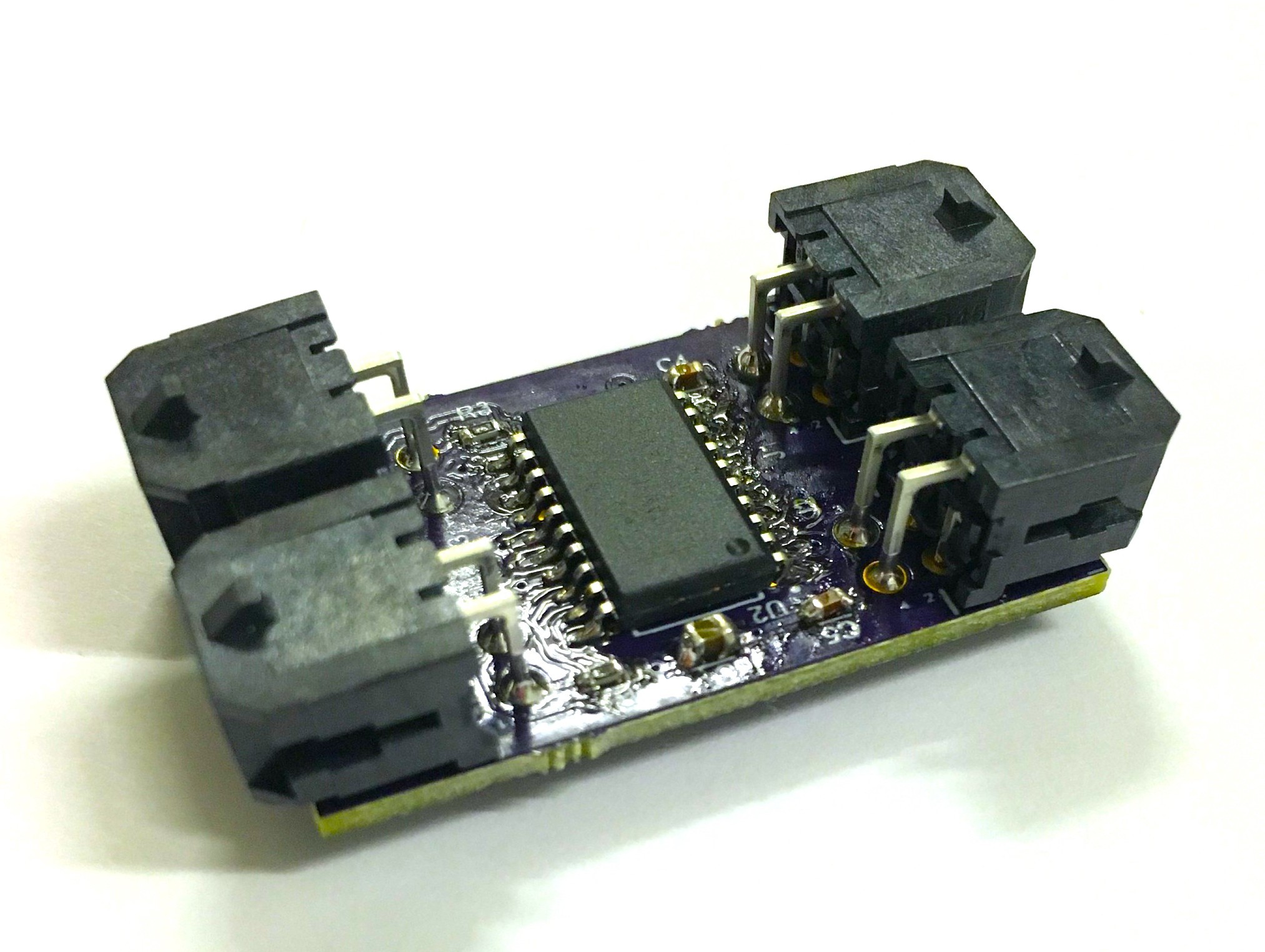
<p>While the buses were generally small enough that we could get away with sub-optimal termination (like putting a single 60Ω termination in the middle of the bus), I thought it would be interesting to design a board to bridge two segments of a CAN bus, allowing each segment to be terminated properly.</p>

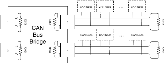
<p>That’s where this project comes in. This board allows up to four separate CAN buses to be connected together and individually terminated, while sharing data between the buses. This enables a quasi-star topology CAN bus, with correct 60Ω impedance on each bus. Each of the four connectors can connect to a different CAN bus. The CAN bridge terminates each connected bus and bridges it to the other buses that are connected. It also bridges 5V power between all of the connectors, and powers itself off the 5V bus.</p>

<p>This diagram shows how this would be wired in a system:
<img src="/assets/images/old_posts/can_bridge_diagram.png" alt="CAN Bridge Diagram" /></p>

<p>And here’s the finished hardware:
<img src="/assets/images/old_posts/can_bridge.jpeg" alt="Finished board" /></p>

<p>Full details here:
<a href="https://github.com/russery/can_bridge">https://github.com/russery/can_bridge</a></p>

<p>You can also follow this project on Hackaday.io:
<a href="https://hackaday.io/project/8490-can-bridge">https://hackaday.io/project/8490-can-bridge</a></p>]]></content><author><name>Robert Ussery</name></author><category term="Electrical Engineering" /><category term="can bus" /><category term="robotics" /><category term="tech guide" /><summary type="html"><![CDATA[This project grew out of a problem we were running into at Airware. The physical layout of some of the aircraft we were putting our autopilot hardware onto made it difficult to properly terminate our CAN buses at each end. In a normal CAN bus, there all of the nodes are connected on a single bus, which is terminated by a 120Ω resistor at each end. The autopilot we had designed had onboard termination for one end of the CAN bus, and then the other end would be terminated at one of the nodes on the bus. This made it difficult to terminate the bus correctly if the autopilot was not physically located at one end of the bus:]]></summary></entry><entry><title type="html">Toilet Monitor Project</title><link href="https://ussery.info/toilet-monitor/" rel="alternate" type="text/html" title="Toilet Monitor Project" /><published>2015-12-28T00:00:00-08:00</published><updated>2015-12-28T00:00:00-08:00</updated><id>https://ussery.info/toilet-monitor</id><content type="html" xml:base="https://ussery.info/toilet-monitor/"><![CDATA[<p>This project grew out of a common source of frustration at our office - we have only three toilets for ~70 employees, and there is frequently contention for this scarce resource. There’s nothing worse than patrolling between the three restrooms searching for an open one.</p>

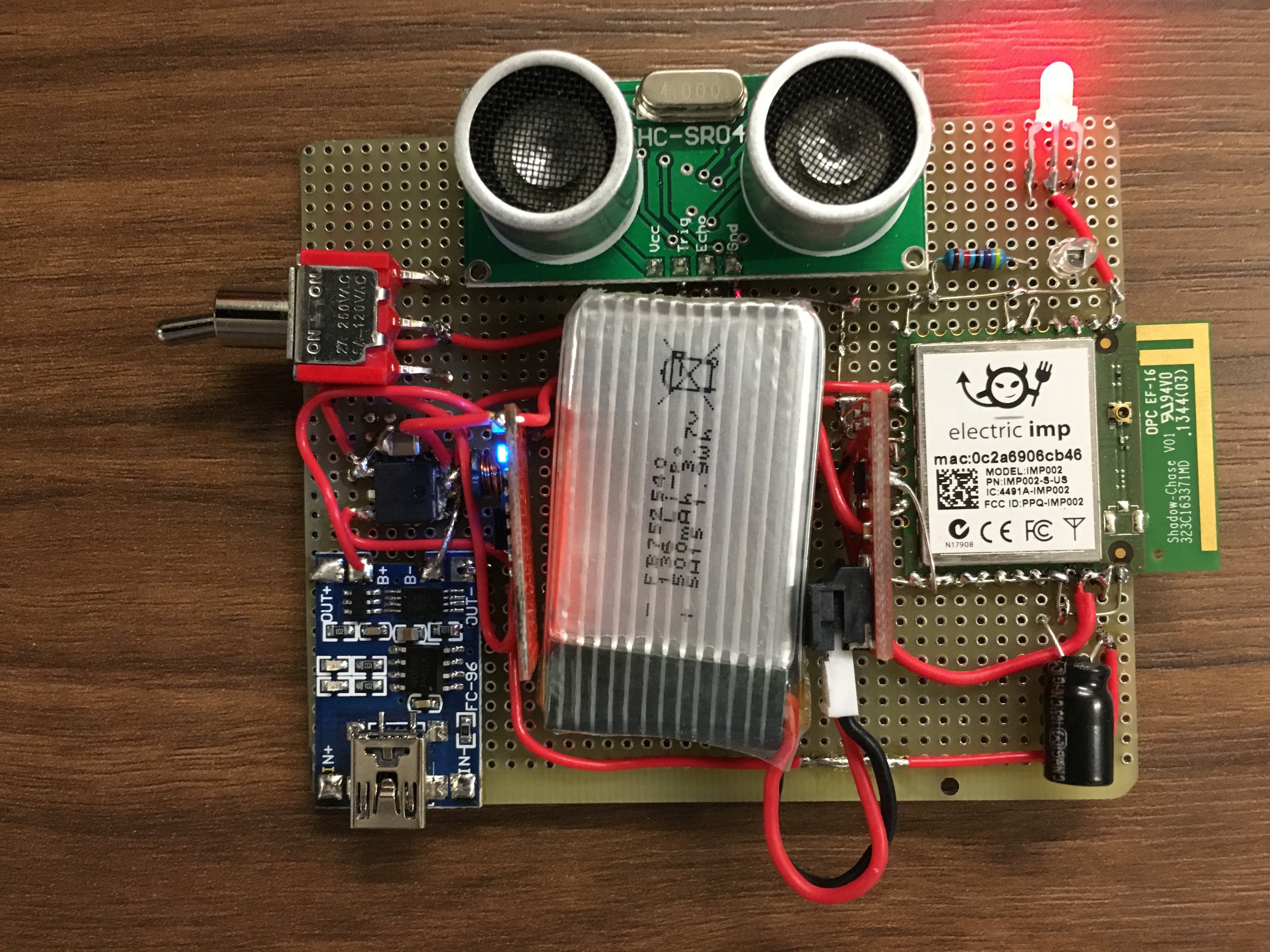
<p>A coworker (Eben) and I started brainstorming how we could solve this issue, and an IoT device seemed the obvious solution. During some booze-infused brainstorming sessions, we came up with the architecture for this, and built it.<!--more-->
<img src="/assets/images/old_posts/toilet_mon_hardware.jpg" alt="Breadboard prototype hardware" /></p>

<p>Full project details are on GitHub:
<a href="https://github.com/russery/toilet_monitor">https://github.com/russery/toilet_monitor</a></p>

<p>You can also follow this project on Hackaday.io:
<a href="https://hackaday.io/project/8377-toilet-monitor">https://hackaday.io/project/8377-toilet-monitor</a></p>]]></content><author><name>Robert Ussery</name></author><category term="Electrical Engineering" /><category term="hackery" /><category term="tech guide" /><summary type="html"><![CDATA[This project grew out of a common source of frustration at our office - we have only three toilets for ~70 employees, and there is frequently contention for this scarce resource. There’s nothing worse than patrolling between the three restrooms searching for an open one. A coworker (Eben) and I started brainstorming how we could solve this issue, and an IoT device seemed the obvious solution. During some booze-infused brainstorming sessions, we came up with the architecture for this, and built it.]]></summary></entry><entry><title type="html">CircuitStudio vs. Altium Designer</title><link href="https://ussery.info/circuitstudio-vs-altium-designer/" rel="alternate" type="text/html" title="CircuitStudio vs. Altium Designer" /><published>2015-11-02T00:00:00-08:00</published><updated>2015-11-02T00:00:00-08:00</updated><id>https://ussery.info/circuitstudio-vs-altium-designer</id><content type="html" xml:base="https://ussery.info/circuitstudio-vs-altium-designer/"><![CDATA[<p><img class="alignleft wp-image-163 size-full" src="/assets/images/old_posts/logo.png" alt="logo" width="204" height="48" />
<p>I signed up for an Altium CircuitStudio trial in the interests of seeing if I can live with it instead of Altium Designer for personal projects. I've been using Altium Designer (AD) at work for a number of years now and love its ease of use, simple workflows, and extremely good schematic-PCB integration.</p>
<p>A little background - Altium now offers three tiers of their eCAD software:</p>
<ul>
<li>Altium Designer - this is their flagship product, targetted at professional users, and runs around $5-10k per license.</li>
<li>Circuit Studio - this is targetted at professionals, and in theory is just a somewhat simplified Altium Designer, and is about half the cost of AD.</li>
<li>Circuit Maker - this is their bottom-end software oriented to the burgeoning Maker community. It is even simpler than Circuit Studio, and has a free version that automatically open-sources your designs unless you pay to keep them private.</li>
</ul>
<p><!--more--></p>
<p>I'm interested in migrating down the tool hierarchy to Circuit Studio or Circuit Maker for my personal projects, where I don't want to use my company's Altium Designer license, but I can't afford to shell out several kilobucks to get my own license. I've been trying out Circuit Studio for a <a href="https://github.com/russery/can_bridge" target="_blank">CAN-Bus bridge project</a> I'm working on in my spare time, and decided to write up my gripes about it here on the blog.</p>
<p>Here are a few other reviews I found useful and interesting:</p>
<ul>
<li><a href="https://www.youtube.com/watch?v=CvMfb95YBgc" target="_blank">Fedevel's Review</a> - FedEvel (Robert Feranec) is a legend in Altium tutorials, and he has a lot of the same gripes as I do</li>
<li><a href="https://www.youtube.com/watch?v=TWcL0OF_eQI" target="_blank">EEVBlog Review</a> - Dave Jones put together a typically bombastic review as well, although he's looking at Circuit Maker, not Circuit Studio. However, it looks like it has a lot of the same problems as Circuit Studio.</li>
</ul>
<h2>Why did they change the keyboard shortcuts?</h2>
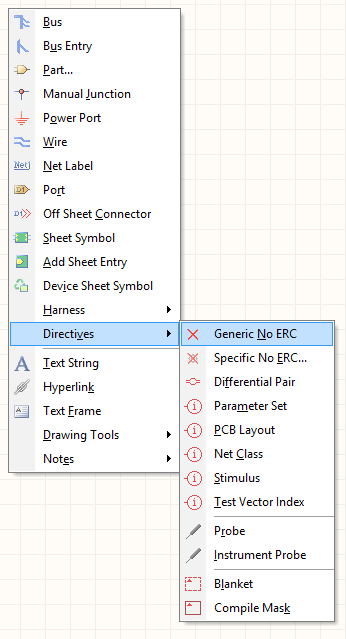
<p>One of the things I totally take for granted using Altium Designer is the convenience afforded by built-in keyboard shortcuts for doing everything from zooming around the document to drawing wires, placing parts, changing alignment, etc. For instance, to place a Generic No-ERC directive, I just type hit the P-V-N keys in that order (<strong>P</strong>lace - Directi<strong>v</strong>e - Generic <strong>N</strong>o ERC). As I do this, the following menus appear at my cursor, showing me what I'm doing:<br />
<a href="/assets/images/old_posts/screen-shot-2015-11-02-at-6-53-04-pm.png"><img class="wp-image-151 size-medium aligncenter" src="/assets/images/old_posts/screen-shot-2015-11-02-at-6-53-04-pm.png?w=162" alt="Altium Designer Shortcut Menu" width="162" height="300" /></a></p>
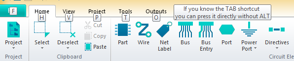
<p>Now in CS, they didn't completely remove the keyboard shortcuts, they just changed and disabled enough of them to make it extremely difficult to transition from AD to CS. For instance, hitting the <strong>P</strong> key no longer brings up the "Place" menu, but rather takes you to the <strong>P</strong>roject menu. To place a component, you have to hit <strong>H</strong> for <strong>H</strong>ome and then a cryptic number for what you want to place. There's not even a way to place a wire without opening the Home menu and clicking the "Wire" button (whereas in AD, I can just hit <strong>P</strong>-<strong>W</strong> and start routing my wire).</p>
<p><a href="/assets/images/old_posts/screen-shot-2015-11-02-at-6-51-36-pm.png"><img class="wp-image-152 size-medium aligncenter" src="/assets/images/old_posts/screen-shot-2015-11-02-at-6-51-36-pm.png?w=300" alt="CircuitStudio Shortcuts" width="300" height="62" /></a></p>
<p>Among the most essential things I can no longer do via shortcut keys:</p>
<ul>
<li>Place a wire in schematics (<strong>P</strong> - <strong>W</strong> in AD)</li>
<li>Zoom to an area (<strong>V</strong> - <strong>A</strong> in AD)</li>
<li>Change the grid size in PCB editor, although this still works in their schematic editor (<strong>G</strong> in AD)</li>
<li>Align components (<strong>A</strong> in AD)</li>
<li>Flip the board in 3D view in PCB editor (<strong>V</strong> - <strong>B</strong> in AD)</li>
</ul>
<p>I'm sure there are a ton others, but these are the ones that have driven me crazy in my couple of hours of playing with CircuitStudio.</p>
<h2>Why can't I import supplier parameters to a part?</h2>
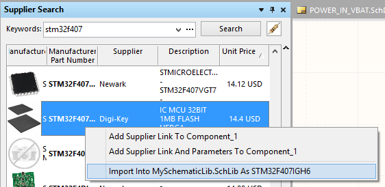
<p>Whereas the keyboard shortcuts issue is an inconvenience, this problem makes CircuitStudio almost unusable for me. In AD, I can use Supplier Search to locate the part I want to create in my schematic library and then right-click on the part and . I use this workflow in AD whether I'm working with standalone .SchLib, an integrated .IntLib, or an .SVNDbLib library.<br />
<img class="size-medium wp-image-153 aligncenter" src="/assets/images/old_posts/screen-shot-2015-11-02-at-7-13-26-pm.png?w=300" alt="AD import part into library" width="300" height="146" /></p>
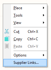
<p>In CS, the best I can do is to add a supplier link to an existing part by right-clicking on the component in my schematic library, and then manually add in all of the parameters.</p>
<p><a href="
/assets/images/old_posts/screen-shot-2015-11-02-at-7-16-29-pm.png"><img class="wp-image-154 aligncenter" src="/assets/images/old_posts/screen-shot-2015-11-02-at-7-16-29-pm.png" alt="CS add supplier link" width="137" height="185" /></a></p>
<p>This is extremely frustrating and time consuming. I think they did this to drive more people to use the Altium-curated CircuitStudio vault, but for anyone who needs to create custom parts with supplier parameters, this is crippling. If you can find all of your parts in their vault, this isn't a show-stopper, but god forbid you have to create a part not in their vault - it'll take you many minutes of frustrating and error prone manual parameter entry.</p>
<h2>They removed the awesome shortcut buttons in the lower right</h2>
<p>This little group of buttons that appears at the lower-right of the screen in Altium Designer is my best friend:</p>
<p><a href="
/assets/images/old_posts/screen-shot-2015-11-02-at-7-19-20-pm.png"><img class="size-medium wp-image-155 aligncenter" src="/assets/images/old_posts/screen-shot-2015-11-02-at-7-19-20-pm.png?w=300" alt="AD shortcut buttons" width="300" height="59" /></a></p>
<p>It allows you to change the view masks, clear any existing masks, change snap options, launch various system panes and a dozen other useful things. Here it is in CircuitStudio:</p>
<p><a href="
/assets/images/old_posts/screen-shot-2015-11-02-at-7-26-12-pm.png"><img class="size-full wp-image-156 aligncenter" src="/assets/images/old_posts/screen-shot-2015-11-02-at-7-26-12-pm.png" alt="CS shortcut buttons" width="250" height="60" /></a></p>
<p>That's right, it doesn't exist anymore. ARRRG! Why, Altium, why?? In order to clear a selection or mask now, I have to navigate to the View Menu and find the Clear button way over on the right side. They didn't even give it a keyboard shortcut, which would have made this somewhat tolerable!</p>
<p><a href="
/assets/images/old_posts/screen-shot-2015-11-02-at-7-18-54-pm.png"><img class="wp-image-157 size-large aligncenter" src="/assets/images/old_posts/screen-shot-2015-11-02-at-7-18-54-pm.png?w=660" alt="CS Clear button location" width="660" height="65" /></a></p>
<h2>Final Thoughts</h2>
<p>All of these things might seem minor, but for someone looking to migrate from Altium Designer to CircuitStudio for personal / side-gig use, this makes it a total non-starter. I can think of a couple reasons Altium might want to do this:</p>
<ol>
<li>They're trying to prevent exactly this migration. They want anyone who's used to using Altium Designer to keep using it, and not be able to move downstream to CircuitStudio. I would have hoped they would just remove some of AD's features that are most useful to a professional like SVNDbLib libraries, advanced PCB routing options, flexible layer stack management, etc. while leaving the interface and user experience alone. This would allow users to more fluidly switch between the two products according to their needs and ability to afford the more advanced package.</li>
<li>They are suffering from a really bad case of <a href="http://i.imgur.com/5IflcaW.png" target="_blank">cranial-rectal inversion</a>. My fear is that they're prototyping new interfaces and workflows for Altium Designer with CircuitStudio, and that this is just the first place we're seeing some of these problems pop up. I'm not sure how much code is shared between the Altium Designer and CircuitStudio products, but hopefully we won't ever see these problems migrated to Altium Designer.</li>
</ol>]]></content><author><name>Robert Ussery</name></author><category term="Altium" /><category term="Circuit Studio" /><category term="Electrical Engineering" /><summary type="html"><![CDATA[I signed up for an Altium CircuitStudio trial in the interests of seeing if I can live with it instead of Altium Designer for personal projects. I've been using Altium Designer (AD) at work for a number of years now and love its ease of use, simple workflows, and extremely good schematic-PCB integration. A little background - Altium now offers three tiers of their eCAD software: Altium Designer - this is their flagship product, targetted at professional users, and runs around $5-10k per license. Circuit Studio - this is targetted at professionals, and in theory is just a somewhat simplified Altium Designer, and is about half the cost of AD. Circuit Maker - this is their bottom-end software oriented to the burgeoning Maker community. It is even simpler than Circuit Studio, and has a free version that automatically open-sources your designs unless you pay to keep them private.]]></summary></entry><entry><title type="html">Teflon Wallet</title><link href="https://ussery.info/teflon-wallet/" rel="alternate" type="text/html" title="Teflon Wallet" /><published>2011-11-14T00:00:00-08:00</published><updated>2011-11-14T00:00:00-08:00</updated><id>https://ussery.info/teflon-wallet</id><content type="html" xml:base="https://ussery.info/teflon-wallet/"><![CDATA[<p><img class="alignleft wp-image-139 size-thumbnail" title="Finished Outside" src="/assets/images/old_posts/img_2035.jpg?w=150" alt="" width="150" height="112" />
<p>I'm going through another minimalist phase, and one of the things that's been bugging me a lot lately is how swollen my wallet has become with all the gift cards, froyo punch cards, random trash, etc. I emptied out my wallet, only to find it didn't really get that much thinner or smaller, because of how massive just the wallet leather is. I started looking around online for a thinner alternative more compatible with my newfound minimalism, and ran across <a href="http://www.instructables.com/id/Paper-Wallet/">this Instructable</a> for making a paper wallet. I was really taken with how compact and simple the paper wallet manages to be, while still being functional and a viable way of carrying cash, credit cards, and identifaction around.</p><!--more-->
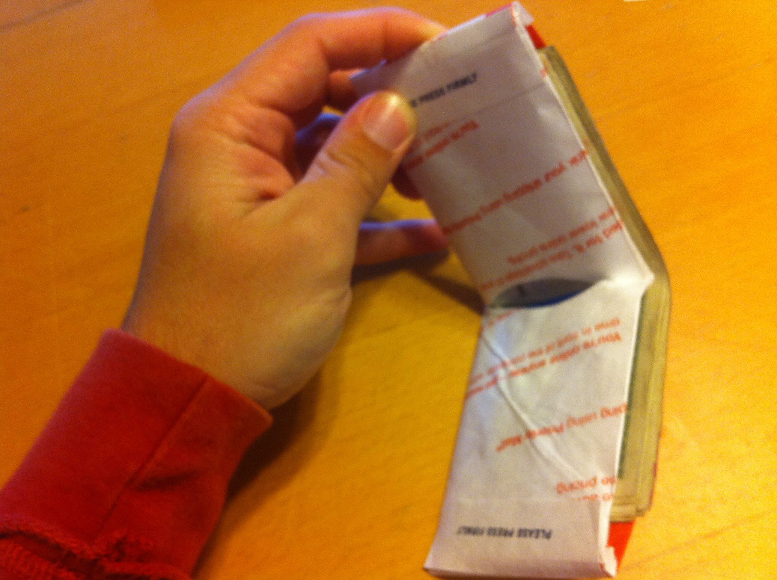
<p>I made myself one of the paper wallets as shown in the Instructable, but realized after a few days of use that it would not last long in an abrasive jeans pocket, and would be absolutely wrecked at the first sign of moisture. I took a brief survey of the paper items around my room which could be more suitable materials for a wallet, and found that I had some USPS Priority Mail envelopes, which are made of a pretty heavy-duty teflon. Here's a quick overview of how I put the wallet together using the envelope:</p>
<p>First off, I sliced open the envelope, and measured out an 8.5 x ll" section, being careful to feature some of the USPS labeling on the section that would become the exterior of the wallet:</p>
<p><a href="/assets/images/old_posts/img_2024.jpg"><img class="aligncenter size-thumbnail wp-image-134" title="Open envelope" src="/assets/images/old_posts/img_2024.jpg?w=150" alt="" width="150" height="112" /></a></p>
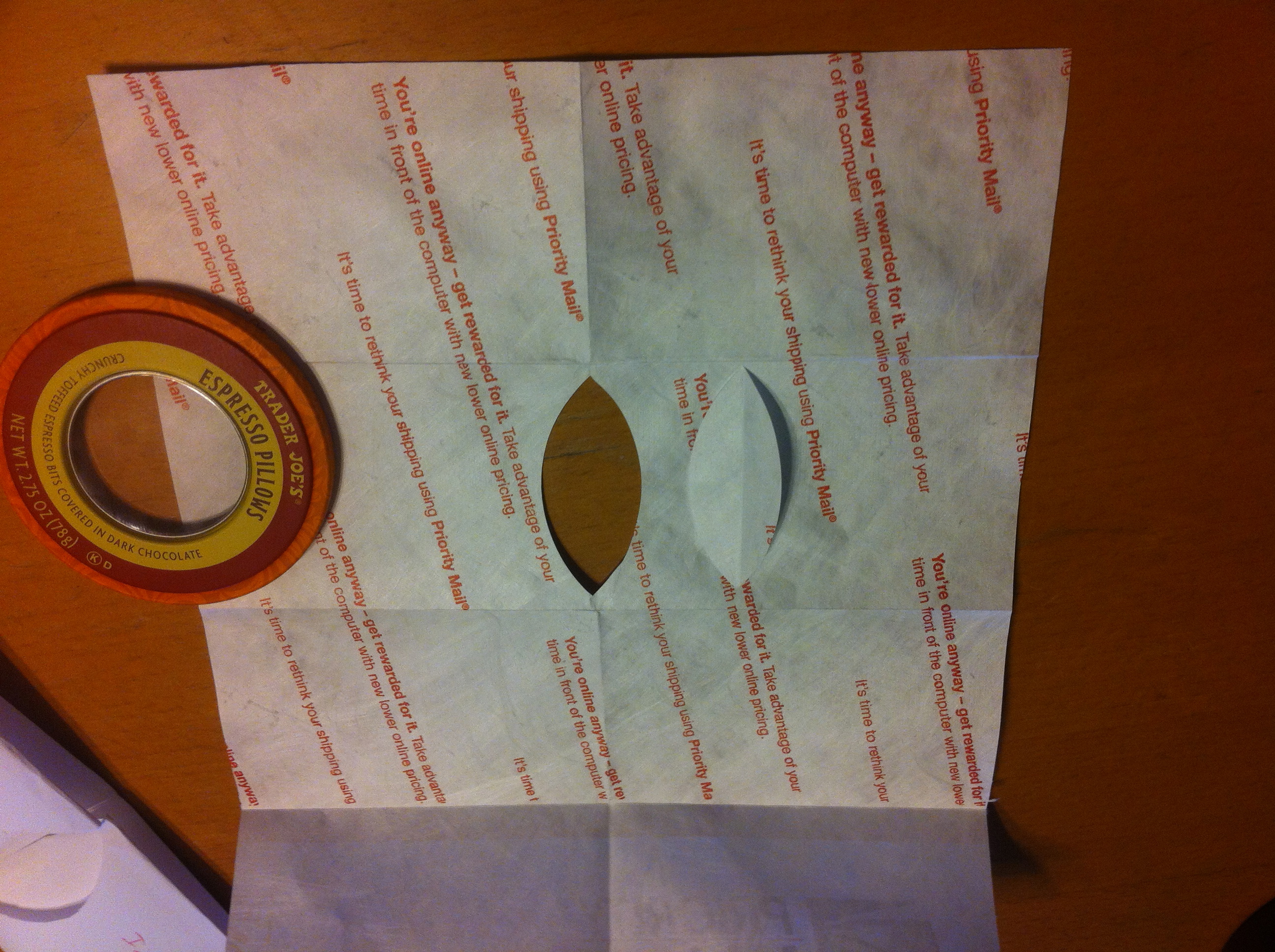
<p>The next step was to cut out the marked off section, and put the initial folds in it, as directed in the paper wallet Instructable. I then sliced out the card openings on the section that would be the inside of the wallet, using a tin can lid as the template:</p>
<p><a href="/assets/images/old_posts/img_2028.jpg"><img class="aligncenter size-thumbnail wp-image-135" title="Inside of wallet" src="/assets/images/old_posts/img_2028.jpg?w=150" alt="" width="150" height="112" /></a></p>
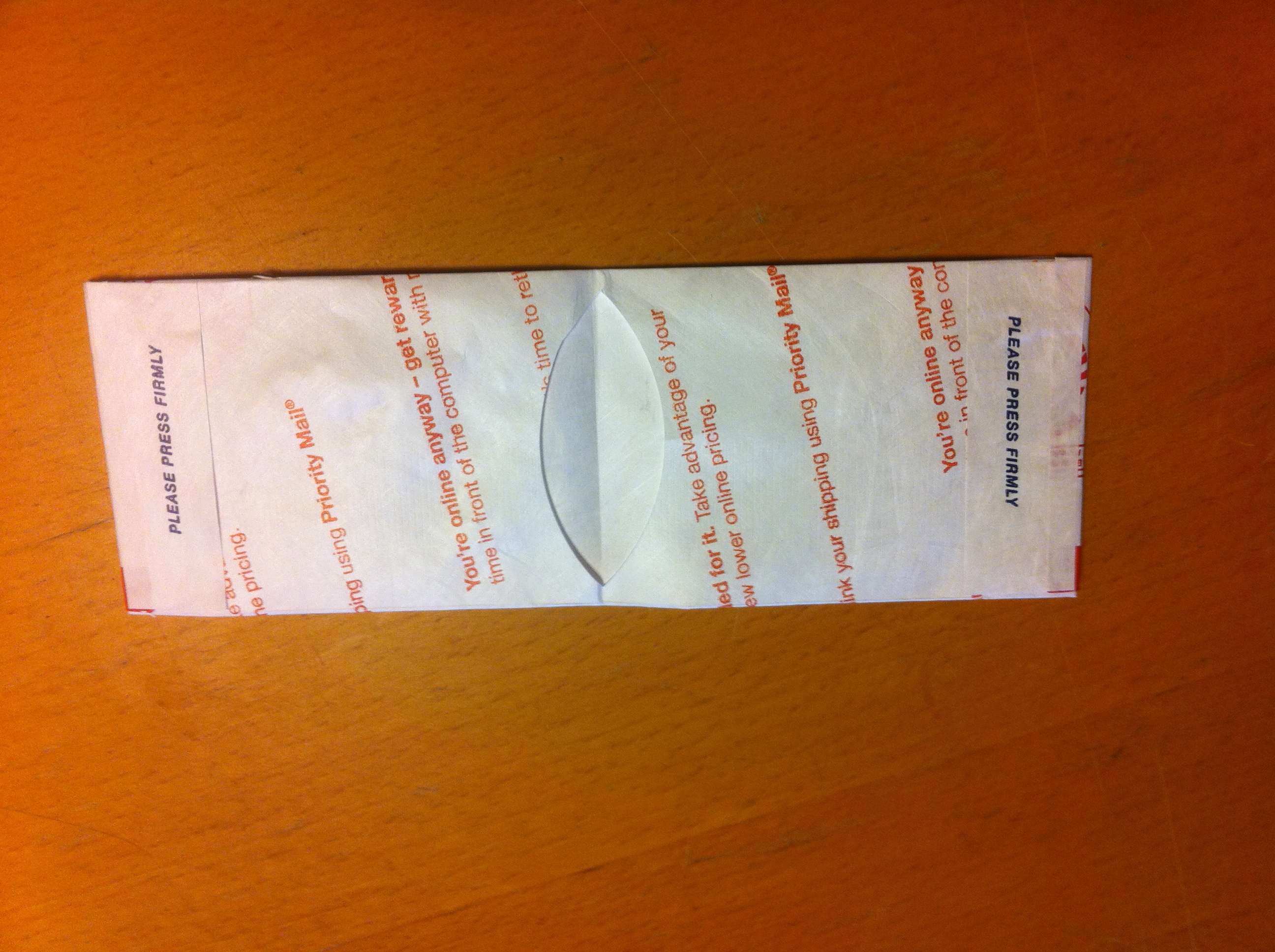
<p>Next, it was a simple matter to perform the final Zipper-cuts as directed in the Instructable, and fold the wallet into its final form:</p>
<p><a href="/assets/images/old_posts/img_2030.jpg"><img class="aligncenter size-thumbnail wp-image-136" title="Folded wallet" src="/assets/images/old_posts/img_2030.jpg?w=150" alt="" width="150" height="112" /></a></p>
<p>One final touch I decided to add to the wallet was to finish the edges with some reinforcing layers, cut from the adhesive-backed flap of the envelope. I cut appropriately sized sections, and applied them to each end and the bottom of the wallet:</p>
<p><a href="/assets/images/old_posts/img_2029.jpg"><img class="aligncenter size-thumbnail wp-image-137" title="Reinforcement" src="/assets/images/old_posts/img_2029.jpg?w=150" alt="" width="150" height="112" /></a></p>
<p>With that, the wallet was finished! I loaded it up and gave it a test run (I'm not normally that rich, but I borrowed some money for the sake of demonstration):</p>
<p><a href="/assets/images/old_posts/img_2034.jpg"><img class="aligncenter size-thumbnail wp-image-138" title="Finished" src="/assets/images/old_posts/img_2034.jpg?w=150" alt="" width="150" height="112" /></a><a href="/assets/images/old_posts/img_2035.jpg"><img class="aligncenter size-thumbnail wp-image-139" title="Finished Outside" src="/assets/images/old_posts/img_2035.jpg?w=150" alt="" width="150" height="112" /></a></p>
<p>I've been using the wallet for about two months now, and it's holding up really well... way better than the previous one I made out of normal paper. Some of the exterior colored bits are starting to wear through, but I think I should get another solid three or so months out of the wallet before making another one. Not bad for a DIY wallet that cost nothing to make!</p>
<p>I've received a ton of compliments on the wallet, with people asking me where I bought it. If I wasn't sure the USPS would sue me, I'd consider selling them on Etsy or something for a hefty markup, but that seems like a risky proposiiton. Anyway, perhaps this will become a trendy way to repurpose all those Priority Mail envelopes after the USPS goes under.</p>]]></content><author><name>Robert Ussery</name></author><category term="fold paper" /><category term="paper wallet" /><category term="Tips and Tricks" /><summary type="html"><![CDATA[I'm going through another minimalist phase, and one of the things that's been bugging me a lot lately is how swollen my wallet has become with all the gift cards, froyo punch cards, random trash, etc. I emptied out my wallet, only to find it didn't really get that much thinner or smaller, because of how massive just the wallet leather is. I started looking around online for a thinner alternative more compatible with my newfound minimalism, and ran across this Instructable for making a paper wallet. I was really taken with how compact and simple the paper wallet manages to be, while still being functional and a viable way of carrying cash, credit cards, and identifaction around.]]></summary></entry><entry><title type="html">GoPro Hero HD 960 Interface Cheat Sheet</title><link href="https://ussery.info/gopro-hero-hd-960-interface-cheat-sheet/" rel="alternate" type="text/html" title="GoPro Hero HD 960 Interface Cheat Sheet" /><published>2011-07-29T00:00:00-07:00</published><updated>2011-07-29T00:00:00-07:00</updated><id>https://ussery.info/gopro-hero-hd-960-interface-cheat-sheet</id><content type="html" xml:base="https://ussery.info/gopro-hero-hd-960-interface-cheat-sheet/"><![CDATA[<p><img class="alignleft wp-image-129 size-thumbnail" title="GoPro HD Hero" src="/assets/images/old_posts/gopro.jpg?w=150" alt="" width="150" height="150" />
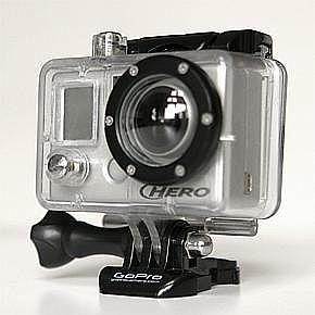
<p>As almost everyone who's used a GoPro can probably attest to, they're amazing little cameras with a completely impossible user interface. I can't count the number of times I've needed to change some setting but couldn't for the life of me remember how, and of course the user manual was long gone.</p>
<p>I made some GoPro cheat sheets that I printed out and then taped to the box where I store the GoPros, so that it'll always be close at hand when I need it. I've even folded up one of the smaller ones and inserted it behind the camera in the waterproof case so it's easy to get to if I need it on the go.</p><!--more-->
<p>I've posted the cheat sheet I put together here, in case it's useful to someone else. There's a pocket sized 4x2" version (<a href="/assets/images/old_posts/gopro-hd-hero-cheat-sheet-4x2inch.pdf">GoPro HD Hero Cheat Sheet 4x2inch</a>), and a larger, easier to read 7x2" version (<a href="/assets/images/old_posts/gopro-hd-hero-cheat-sheet-7x4inch.pdf">GoPro HD Hero Cheat Sheet 7x4inch</a>), both in .pdf format. I've also posted the excel file I used to create them (<a href="/assets/images/old_posts/gopro-hd-hero-cheat-sheet.xlsx">GoPro HD Hero Cheat Sheet Excel File</a>), in case you want to modify them to suit your particular tastes.</p>
<h3>Files:</h3>
<ul>
<li><a href="/assets/images/old_posts/gopro-hd-hero-cheat-sheet.xlsx">GoPro HD Hero Cheat Sheet Excel File</a> (57kB .xlsx)</li>
<li><a href="/assets/images/old_posts/gopro-hd-hero-cheat-sheet-7x4inch.pdf">GoPro HD Hero Cheat Sheet 7x4inch</a> (45kB .pdf)</li>
<li><a href="/assets/images/old_posts/gopro-hd-hero-cheat-sheet-4x2inch.pdf">GoPro HD Hero Cheat Sheet 4x2inch</a> (49kB .pdf)</li>
</ul>]]></content><author><name>Robert Ussery</name></author><category term="GoPro HD" /><category term="HD Hero 960" /><category term="Tips and Tricks" /><category term="User Manual" /><summary type="html"><![CDATA[As almost everyone who's used a GoPro can probably attest to, they're amazing little cameras with a completely impossible user interface. I can't count the number of times I've needed to change some setting but couldn't for the life of me remember how, and of course the user manual was long gone. I made some GoPro cheat sheets that I printed out and then taped to the box where I store the GoPros, so that it'll always be close at hand when I need it. I've even folded up one of the smaller ones and inserted it behind the camera in the waterproof case so it's easy to get to if I need it on the go.]]></summary></entry><entry><title type="html">Chip Yates Electric Motorcycle</title><link href="https://ussery.info/chip-yates-electric-motorcycle/" rel="alternate" type="text/html" title="Chip Yates Electric Motorcycle" /><published>2010-10-25T00:00:00-07:00</published><updated>2010-10-25T00:00:00-07:00</updated><id>https://ussery.info/chip-yates-electric-motorcycle</id><content type="html" xml:base="https://ussery.info/chip-yates-electric-motorcycle/"><![CDATA[<figure class="">
  
  <img src="/assets/images/old_posts/swigz-pro-racing-superbike-630.webp"
       alt=""
       width="100%">
  
  
</figure>
<p><a href="https://www.autoblog.com/2010/10/24/chip-yates-reveals-kers-secret-of-swigz-superbike-w-video/">
This is a pretty cool article</a> describing some of the up-till-now secret sauce on the electric motorcycle project I've been working on with Chip Yates for the last few months. The article describes the front-wheel Kinetic Energy Recovery System that Chip designed in great detail. It has some cool pictures of the bike, and an awesome video that someone (ahem, yours truly) put together for the bike unveiling a few weeks ago.</p><!--more-->]]></content><author><name>Robert Ussery</name></author><category term="Electric Motorcycle" /><category term="engineering" /><summary type="html"><![CDATA[This is a pretty cool article describing some of the up-till-now secret sauce on the electric motorcycle project I've been working on with Chip Yates for the last few months. The article describes the front-wheel Kinetic Energy Recovery System that Chip designed in great detail. It has some cool pictures of the bike, and an awesome video that someone (ahem, yours truly) put together for the bike unveiling a few weeks ago.]]></summary></entry><entry><title type="html">GTI Subwoofer Install</title><link href="https://ussery.info/gti-subwoofer-install/" rel="alternate" type="text/html" title="GTI Subwoofer Install" /><published>2010-06-06T00:00:00-07:00</published><updated>2010-06-06T00:00:00-07:00</updated><id>https://ussery.info/gti-subwoofer-install</id><content type="html" xml:base="https://ussery.info/gti-subwoofer-install/"><![CDATA[<p><a href="http://farm5.static.flickr.com/4071/4673248694_4b7f541578_b.jpg"><img class="alignleft" title="Finished Install" src="/assets/images/old_posts/4673248694_4b7f541578_m.jpg" alt="" width="240" height="180" /></a>
<p>I've been a wannabe car audio nut for quite a while, but I've never really had the time, money, and inspiration to actually do anything until recently. When I had my Miata, I had planned on installing an 8" sub in the trunk in a custom fiberglass enclosure. I even went so far as to build up a foam mockup of it, but that mockup just sat on my shelf for four years of college and never got built.</p><!--more-->
<p>Now that I'm working and have more dollars than sense and finally have a car that's big enough to hold a decent audio setup, I finally decided to buckle down and install a woofer. Following is a writeup of my install. I bought my GTI back in May 2009, and I've been pretty happy with the stock sound system except for the lack of bass. If I turned up the bass control knob at all, it would just distort and sound horrible. Otherwise, the stock system was pretty clean and loud however. I haven't been really impressed with any of the aftermarket head unit installs I've seen in GTI's, so I decided to keep the stock head unit and the stock speakers, at least for the time being. After surfing the forums and discussing it with some audio-nut friends, I decided a single 8" or 10" sub would likely do for my needs.</p>
<p>
<a href="http://farm5.static.flickr.com/4060/4673353000_6a15180476_b.jpg"><img title="Beautiful, ain't it?" src="/assets/images/old_posts/4673353000_6a15180476_m.jpg" alt="The GTI" width="240" height="180" /></a>
</p>
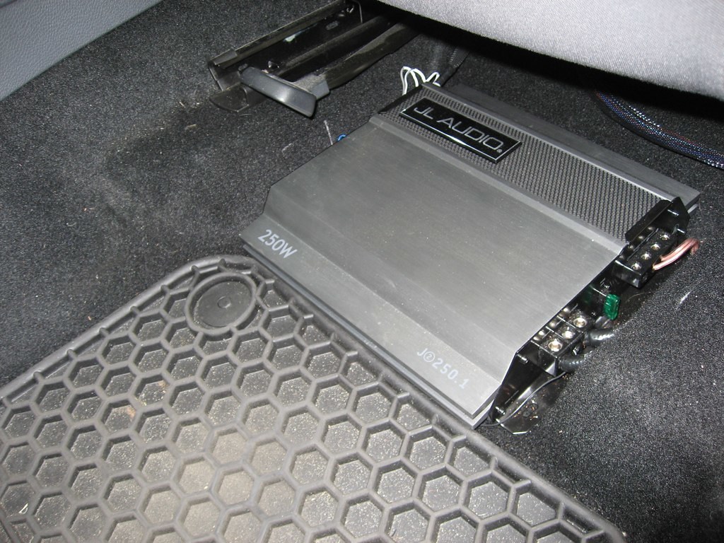
<p>Because the stock system maxes out at about 20W per channel, I figured I should take it pretty easy with the wattage I put in for my woofer, so as not to overpower the stock system and end up with nothing more than a deafening back massager. After shopping around a little and reading amp reviews, I settled on a JL 250.1 mono amp. I had been wanting to mount the amplifier under my drivers seat since there's a nice little cutout there, and as it turns out this JL amp is an absolutely perfect fit for the space.</p>
<p>Having selected the amp, I started hunting for subs and enclosures. I contemplated making my own MDF enclosure to fit toward the side of the trunk, but I ran across a beautiful <a href="http://www.audiointegrations.net/catalog/item/7242239/7469810.htm" target="_blank">fiberglass enclosure from Audio Integrations</a> that tucks back into one of the wheel well cubbies in the trunk. I decided to buy a JL sub just to keep my components from the same manufacturer, for no better reason than that I knew JL made good components and my OCD likes having everything uniform. I grabbed a <a href="http://mobile.jlaudio.com/products_subs.php?series_id=15" target="_blank">JL 10W1V2</a> subwoofer, since its volume requirements fit the AI box and it had good reviews.</p>
<p>
<a href="http://farm5.static.flickr.com/4013/4673244830_dc23038810_b.jpg"><img title="Before Shot" src="/assets/images/old_posts/4673244830_dc23038810_m.jpg" alt="empty trunk" width="240" height="180" /></a>
</p>
<p>Finally, I drew up a whole system diagram and estimated how much wire and overbraid I'd need for the install, and made sure I had all the hardware I'd need. I've always found the most frustrating thing in the world is getting partially through an install and finding that you don't have one piece of hardware to finish it up. I ordered all the stuff from Crutchfield, and sat on the edge of my chair until it arrived a week or so later.</p>
<p>Once I received all the components, I wired it together on my bedroom floor with a lab power supply stolen from one of my roommates, to make sure I knew how I was going to hook it up. I wired up a potentiometer with a built-in switch to the remote volume control and the remote turn-on inputs of the amplifier in place of the stock remote volume knob. The pot replaces the remote volume control, while the switch mechanism disables the remote-on line. I terminated the control lines from the pot into a short pigtail with a connector on the end, so that I could modify it or replace it down the line without modifying the other amp wiring if I need to.</p>
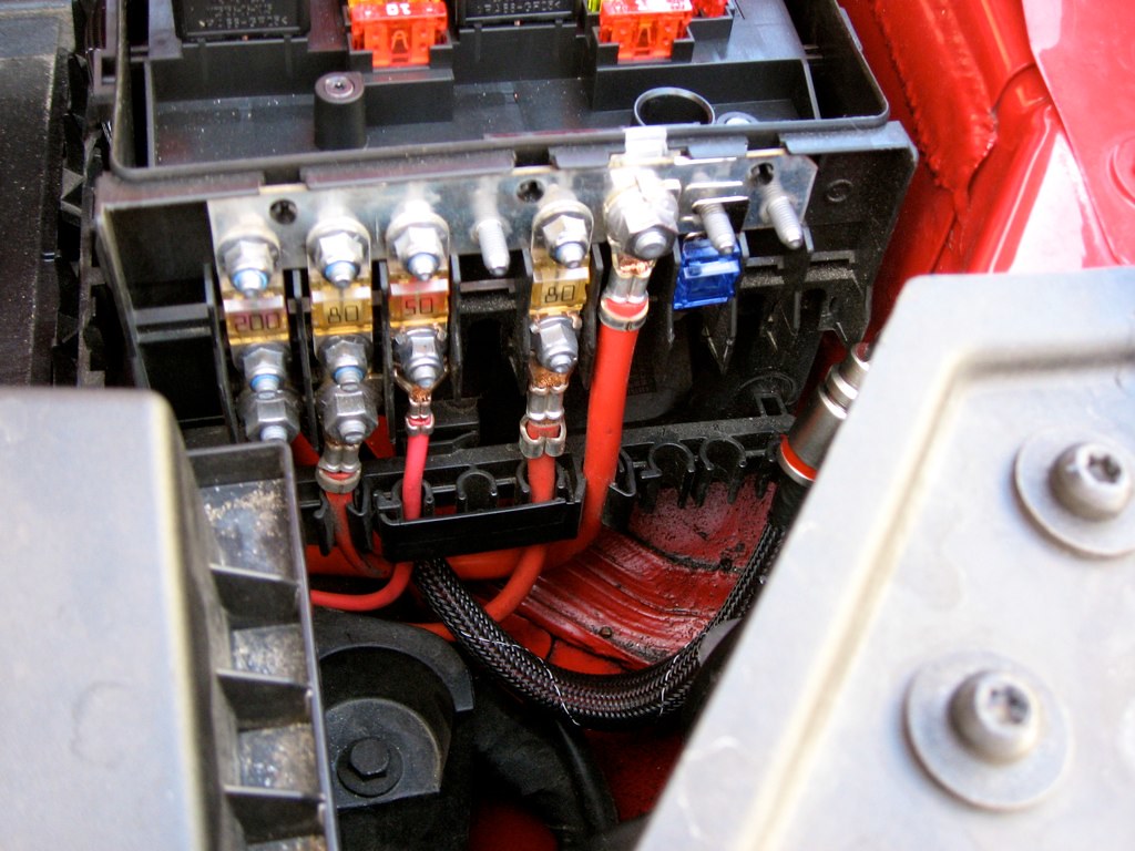
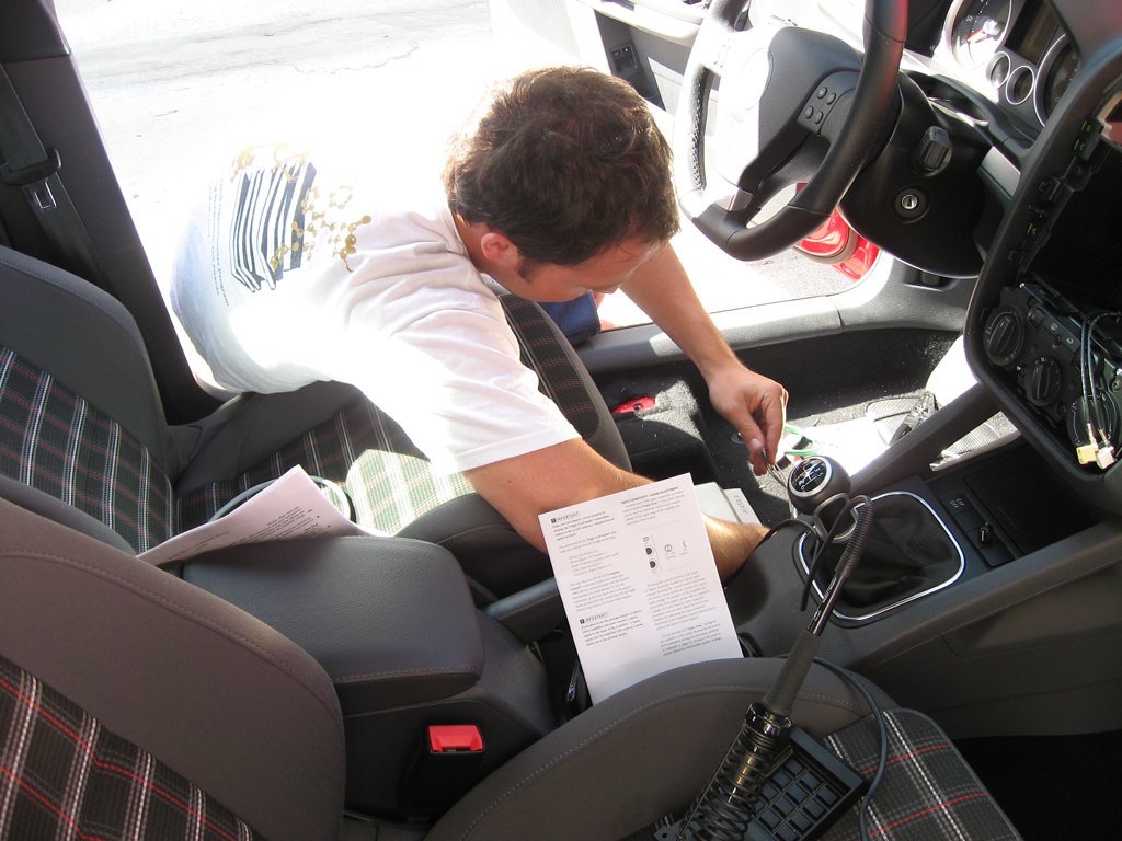
<p>Finally, install day rolled around. My buddy James drove down from LA to assist and advise, since he's had some experience with previous audio installs. I decided to tackle routing the power cables first. I had purchased some 4AWG power wire to use for power and ground from the amp. I lucked out in that Volkswagen has a big distribution bus bar in the main fusebox under the hood with a few empty positions. This made it really easy to mount a fuse and source power for the amp.</p>
<p>
<a href="http://farm5.static.flickr.com/4002/4672897863_bcc8206ce6_b.jpg"><img title="fuse block" src="/assets/images/old_posts/4672897863_bcc8206ce6_m.jpg" alt="fuses!" width="240" height="180" /></a>
</p>
<p>I had to modify the front of the fuse block a little by cutting down some of the plastic below the bus bar to provide clearance for the new terminal. However, you can't see the modified bits at all when the fuse box cover is installed. In the photo above, you can see the 4AWG wire in black overbraid running below the front of the fuse box and the purple 60A fuse I used for the amplifier.</p>
<p>
<a href="http://farm5.static.flickr.com/4007/4672624755_b70e0600fe_b.jpg"><img title="Finished fuse block" src="/assets/images/old_posts/4672624755_b70e0600fe_m.jpg" alt="" width="240" height="180" /></a>
</p>
<p>Routing the power wire through the firewall also turned out to be easier than I had anticipated. I found a large rubber boot with the main engine harness running through it just behind the battery box. This boot had a number of small "nipples" on it for additional harnesses to run through, so I clipped off one of the spare nipples and fed the power wire through from the passenger compartment. The rubber boot forms a very tight seal against the cable insulation, so I'm not concerned about water being able to migrate in from the engine compartment.</p>
<p>
<a href="http://farm5.static.flickr.com/4042/4672619791_dacd0c79a1_b.jpg"><img title="Rubber firewall boot" src="/assets/images/old_posts/4672619791_dacd0c79a1_m.jpg" alt="" width="180" height="240" /></a>
</p>
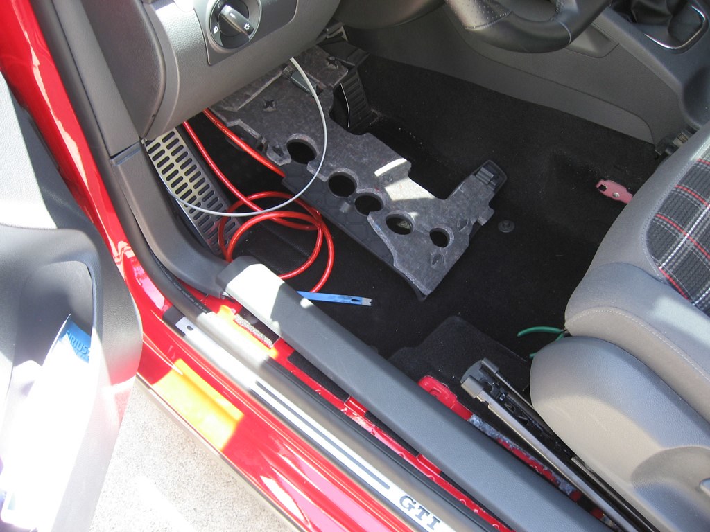
<p>To route the power cable to the amplifier location under the seat required removing a large plastic panel under the steering wheel, several trim pieces near the door, and the drivers' seat. I had heard that disconnecting the airbag harness going to the drivers' seat can cause issues with the airbag system, so I did not completely remove the seat but rather just removed the hold-down bolts and slid it into the rear seat footwell. I removed the door sill trim piece, and the trim piece that the hood release mounts to.</p>
<p>
<a href="http://farm2.static.flickr.com/1273/4672620307_19d8fce44a_b.jpg"><img title="Routing wires" src="/assets/images/old_posts/4672620307_19d8fce44a_m.jpg" alt="" width="240" height="180" /></a>
</p>
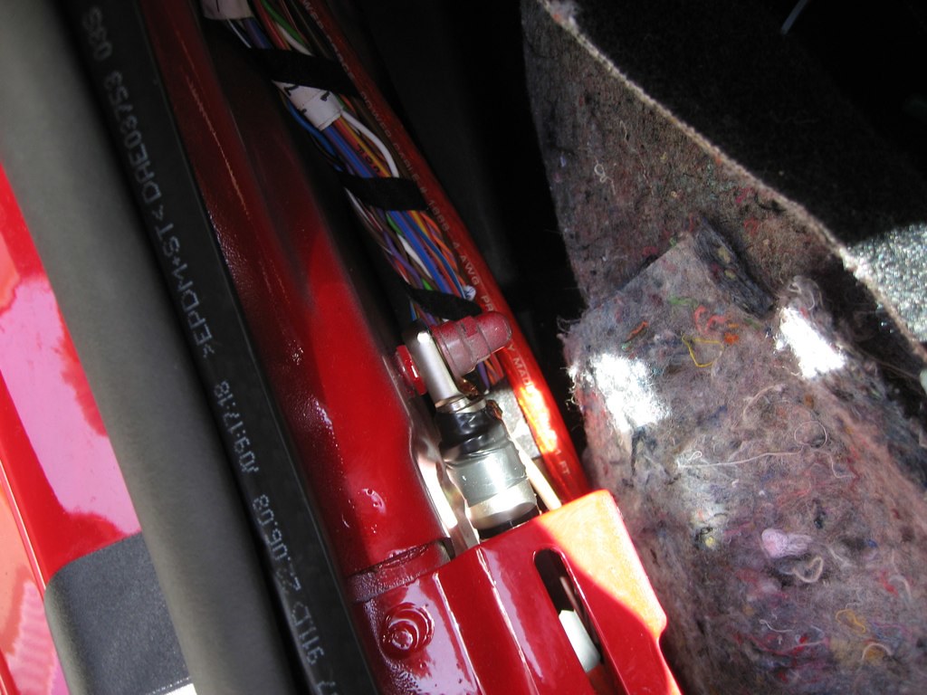
<p>I routed the power cable down underneath the door sill and then out under the seat. There's a pretty sizable tunnel under the door sill that made routing the cable very easy. I also found a large grounding bolt in the tunnel which I decided to use for the amplifier ground. I'm not sure what the ground wire attached to the bolt goes to, but based on subsequent events (keep reading) I think it might be associated with the airbag system.</p>
<p>
<a href="http://farm5.static.flickr.com/4046/4672621029_827af95078_b.jpg"><img title="Grounding point" src="/assets/images/old_posts/4672621029_827af95078_m.jpg" alt="" width="240" height="180" /></a>
</p>
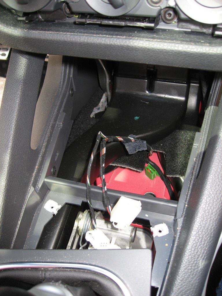
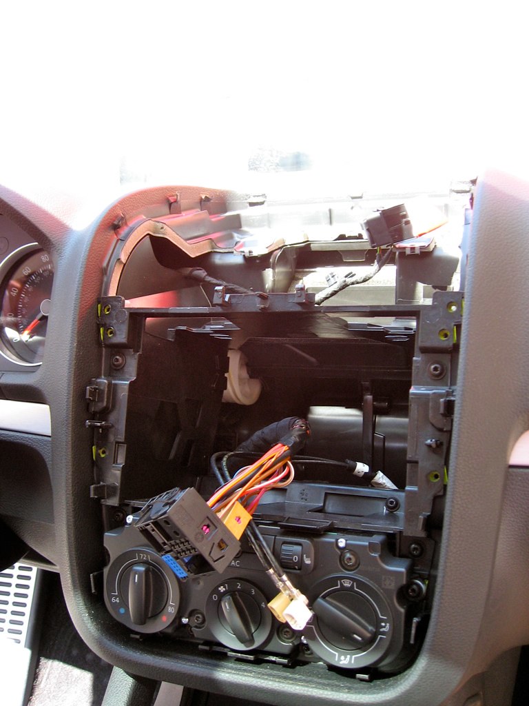
<p>I ran the ground wire up the tunnel under the drivers' seat along with the power wire. With the power cables routed, my next step was to wire in to the back of the head unit. Following some instructions I found online, I pulled the dashboard apart, and removed the head unit. Once I had access to the head unit harness, I used some Positaps to connect a length of 8-conductor shielded 24AWG wire to the rear speaker outputs. I used four of the conductors to carry the line-level audio to the amp, two for the level control, and one for the remote-turnon, leaving one spare conductor.</p>
<p>
<a href="http://farm5.static.flickr.com/4012/4673246962_520f35a9e3_b.jpg"><img title="Pulled-apart dash" src="/assets/images/old_posts/4673246962_520f35a9e3_m.jpg" alt="" width="180" height="240" /></a>
</p>
<p>After tapping the speaker outputs, I reinstalled the head unit and put the dash back together. I routed the cable from the rear of the head unit down through the center tunnel and then out under the driver's seat. I pulled out the ashtray assembly and mounted the level control pot on one of the blank switch plates next to the ESP switch. I had to cut away a decent bit of plastic from the ashtray assembly to clear the pot body, and I'm not very happy with the mounting, so I'll probably re-do it one of these days when I have some down-time.</p>
<p>
<a href="http://farm5.static.flickr.com/4009/4673247506_0d4ffa10ac_b.jpg"><img title="Removed Ashtray" src="/assets/images/old_posts/4673247506_0d4ffa10ac_m.jpg" alt="" width="180" height="240" /></a>
</p>
<p>The last step before actually installing the amp was to route the wires back to the sub. This actually turned out to be substantially easier than I had feared. I was figuring I'd have to route the wires under the carpet and possibly remove the back seat to get them back to the trunk cleanly. As it turns out, however, I was able to just slide them under the plastic trim panels along the side of the car and then along the side of the rear seat. I pulled up the carpet covering the spare tire and ran the wire along the styrofoam that holds the spare in place. In this picture, you can barely see the wire in its black overbraid next to the lower rear seat bolster and right near the hinge where the seat folds down:</p>
<p>
<a href="http://farm2.static.flickr.com/1290/4673249792_5c036cb1fc_b.jpg"><img title="Sub wire routing" src="/assets/images/old_posts/4673249792_5c036cb1fc_m.jpg" alt="" width="180" height="240" /></a>
</p>
<p>Finally, I installed the amp itself under the drivers' seat. This required terminating the volume control wires in a 3.5mm audio plug, splicing the speaker level inputs to the JL-supplied connector pigtail, and connecting the remote turn-on wire to the remote input on the amp. I connected the 4AWG power wires as well as the sub outputs.</p>
<p>
<a href="http://farm5.static.flickr.com/4063/4672622691_51d7959722_b.jpg"><img title="Wiring the amp" src="/assets/images/old_posts/4672622691_51d7959722_m.jpg" alt="" width="240" height="180" /></a>
</p>
<p>I was pretty squeamish about drilling holes in the floor to attach the amp, so I decided to go with the tried and true velcro mounting method. I put some large velcro adhesive patches to the bottom of the amp, and stuck it in place on the floor. Frequent removal would probably tear up the carpet pretty badly, but I don't anticipate I'll be pulling the amp out frequently. Here's the final amp install:</p>
<p>
<a href="http://farm5.static.flickr.com/4060/4672623161_4427f13e92_b.jpg"><img title="Final amplifier install" src="/assets/images/old_posts/4672623161_4427f13e92_m.jpg" alt="" width="240" height="180" /></a>
</p>
<p>The amp is completely stealth when the driver's seat is in a normal driving position. It can only be seen if you're really looking for it:</p>
<p>
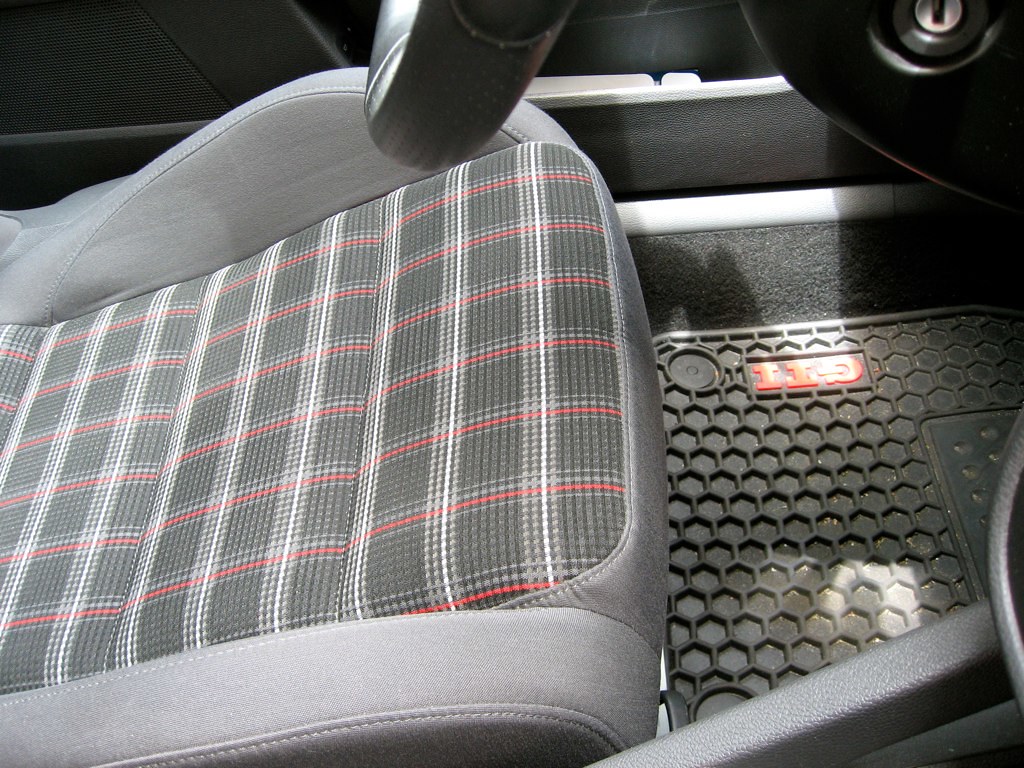
<a href="http://farm2.static.flickr.com/1306/4675473841_ea5cd854b4_b.jpg"><img title="Invisible amp install" src="/assets/images/old_posts/4675473841_ea5cd854b4_m.jpg" alt="" width="240" height="180" /></a>
</p>
<p>The sub box install was ridiculously easy. Audio Integrations makes a really well-built product that just dropped right in. The only hitch I ran into was getting the installation bolts to slide cleanly into the enclosure, so I dropped a 1/4" drill bit into the installation holes to smooth and widen them out a little. The final installation is really clean, and almost looks stock because Audio Integrations did a really good job of matching the OEM carpet:</p>
<p>
<a href="http://farm5.static.flickr.com/4071/4673248694_4b7f541578_b.jpg"><img title="Woofer instlalation" src="/assets/images/old_posts/4673248694_4b7f541578_m.jpg" alt="" width="240" height="180" /></a>
</p>
<p>I'm really pleased with the install... I think the 10" sub is a perfect fit for the stock stereo. With the amp volume control set about halfway, the system sounds pretty well balanced. If I want to really shake and do some hearing damage, I can turn it up all the way and get all the mirrors shaking. I've got a few outstanding issues with the install that I need to fix:</p>
<ul>
<li>The airbag warning light came on right after the install, along with a MFD warning saying "Airbag Fault". I've read mixed stories on the forums about this issue. Some people have reported the same issue from just disconnecting the battery, but other people have said it's an indication of some larger problem. I'm mildly concerned that disconnecting that ground wire to install the amp ground might have caused the fault condition. I'll be taking the car in to the dealer in a week or two for the 20,000 mile service, so I guess I'll find out then what the issue is.</li>
<li>The pot that I used for the level control is a linear-resistance pot. Unfortunately, it looks like the amp level control is designed for a logarithmic "audio" pot. I'm hunting around for a suitable replacement log pot, but for the time being it's usable. The effect of using a linear vs a log pot is that the useful range of the pot is compressed to one end of its rotation. Most of the volume control takes place in the first 1/4 turn of the pot. I'm still shopping around for a suitable audio pot, but one of these days I'll swap it out.</li>
</ul>
<p>*UPDATE 6/12/2010* I brought the GTI in to the dealer, and the airbag fault code was apparently due to an unexpected open circuit on the passenger airbag warning light in the center of the dash. This was due to me disconnecting it while pulling the dash apart to get at the back of the head unit, even though I reconnected it when I was done. It might be possible to pull the dash apart without disconnecting this light, but I haven't tried it.Anyway, the dealer cleared the fault code at no cost, and now everything's back to normal.</p>]]></content><author><name>Robert Ussery</name></author><category term="Audio Upgrade" /><category term="GTI" /><category term="JL" /><category term="King Kong in tha Trunk" /><category term="Subwoofer" /><category term="Volkswagen" /><summary type="html"><![CDATA[I've been a wannabe car audio nut for quite a while, but I've never really had the time, money, and inspiration to actually do anything until recently. When I had my Miata, I had planned on installing an 8" sub in the trunk in a custom fiberglass enclosure. I even went so far as to build up a foam mockup of it, but that mockup just sat on my shelf for four years of college and never got built.]]></summary></entry><entry><title type="html">Airport Express Power Supply Repair</title><link href="https://ussery.info/airport-express-power-supply-repair/" rel="alternate" type="text/html" title="Airport Express Power Supply Repair" /><published>2009-03-25T00:00:00-07:00</published><updated>2009-03-25T00:00:00-07:00</updated><id>https://ussery.info/airport-express-power-supply-repair</id><content type="html" xml:base="https://ussery.info/airport-express-power-supply-repair/"><![CDATA[<p><img class="alignleft" title="before" src="/assets/images/old_posts/3386314146_26612daf9a_m.jpg" alt="" width="240" height="180" />
<p>I bought an Apple Airport Express off Craigslist a couple months ago so I can send music to my living room stereo via Airtunes. The little bugger quit working about a month in though, so I tossed it in a drawer to be put on Ebay for scrap or otherwise dealt with. As is wont to happen this semester, however, one day recently I got bored and went hunting around my room for things to do. I ran across the Airport Express and started wondering what was wrong with it. Here's the story of the teardown and my attempts at repairing it:</p>
<p><!--more--></p>
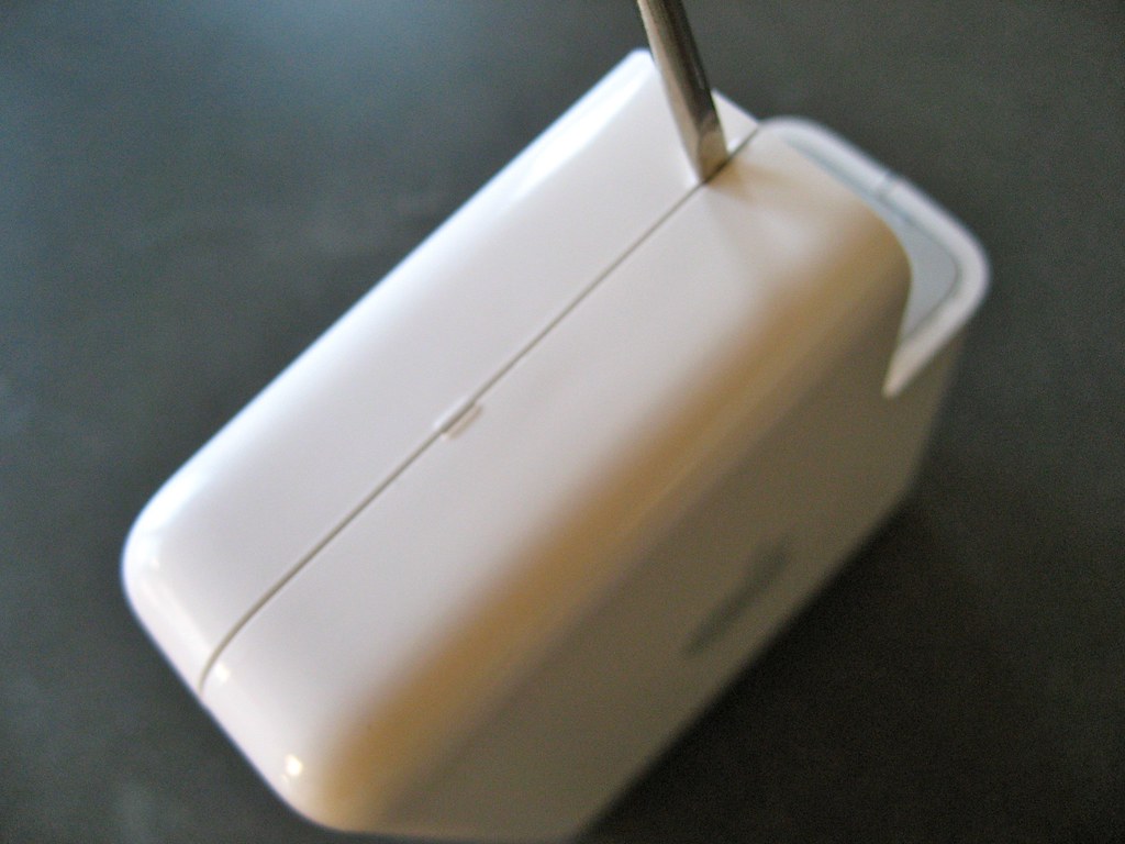
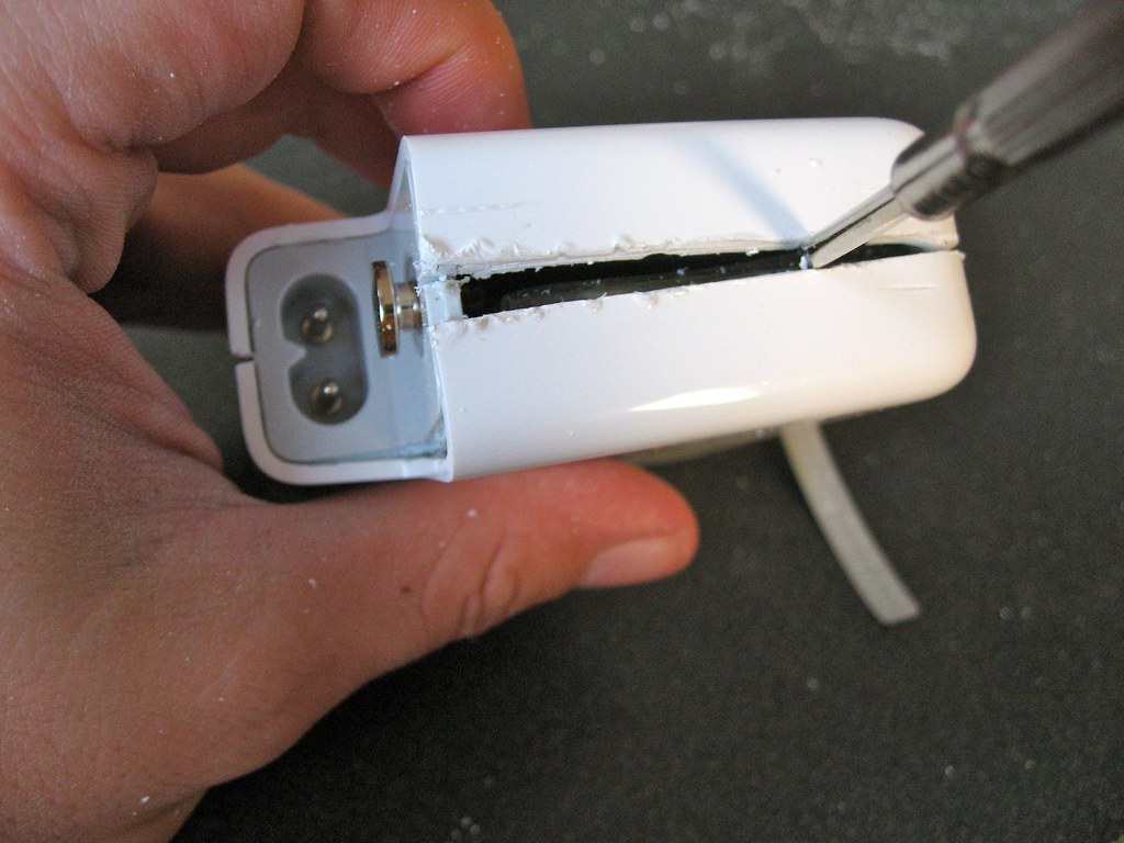
<p>Apple, being Apple, decided to make it im-freaking-possible to get into the guts of the Airport Express. The case is two halves of thick plastic ultrasonically welded together, making it a serious pain in the ass to get it open. I tried prying it apart with a series of screwdrivers:</p>
<p>
<a href="http://farm4.static.flickr.com/3627/3386315052_fd0b828973_b.jpg"><img title="prying" src="/assets/images/old_posts/3386315052_fd0b828973_m.jpg" alt="Attempting to pry it open" width="240" height="180" /></a>
</p>
<p>This was the wrong way to go about it. After a half hour of struggling with various sizes of screwdriver, I got impatient and grabbed my hand-saw. I carefully sawed around the three sides without the connectors. I tried to saw down the plastic until I was just starting to break through to the inside of the box, but this was pretty tricky in spots. Eventually I got impatient and went back to the screwdrivers:</p>
<p>
<a href="http://farm4.static.flickr.com/3465/3386313820_36cf878ecb_b.jpg"><img title="prying" src="/assets/images/old_posts/3386313820_36cf878ecb_m.jpg" alt="Back to screwdrivers" width="240" height="180" /></a>
</p>
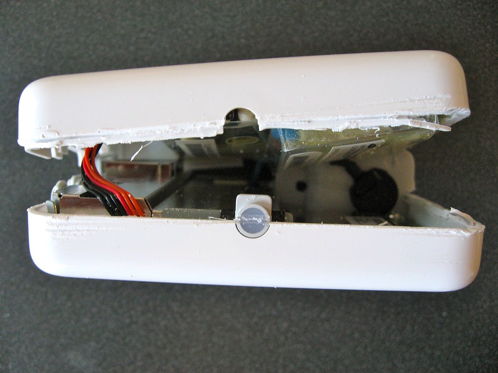
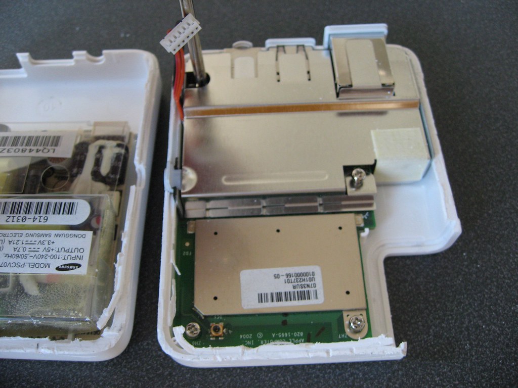
<p>After a good bit of prying and swearing, I managed to get the thing open. The Airport Express internals are split into two halves... a power board, and the airport-express-stuff board, with just a power cable connecting the two:</p>
<p>
<a href="http://farm4.static.flickr.com/3555/3385501751_d426742622_b.jpg"><img title="Halved" src="/assets/images/old_posts/3385501751_d426742622_m.jpg" alt="Halved" width="240" height="180" /></a>
</p>
<p>Once the Airport Express is open, there are a few screws holding the Airport motherboard in place. I pulled those screws and then popped the metal shielding off of the board.</p>
<p>
<a href="http://farm4.static.flickr.com/3544/3385504019_a764145df8_b.jpg"><img title="Guts" src="/assets/images/old_posts/3385504019_a764145df8_m.jpg" alt="Airport motherboard" width="240" height="180" /></a>
</p>
<p>Here's what the two boards look like after yanking them from the plastic shells:</p>
<p>
<a href="http://farm4.static.flickr.com/3589/3385502525_3755c63720_b.jpg"><img title="halved" src="/assets/images/old_posts/3385502525_3755c63720_m.jpg" alt="The boards" width="240" height="180" /></a>
</p>
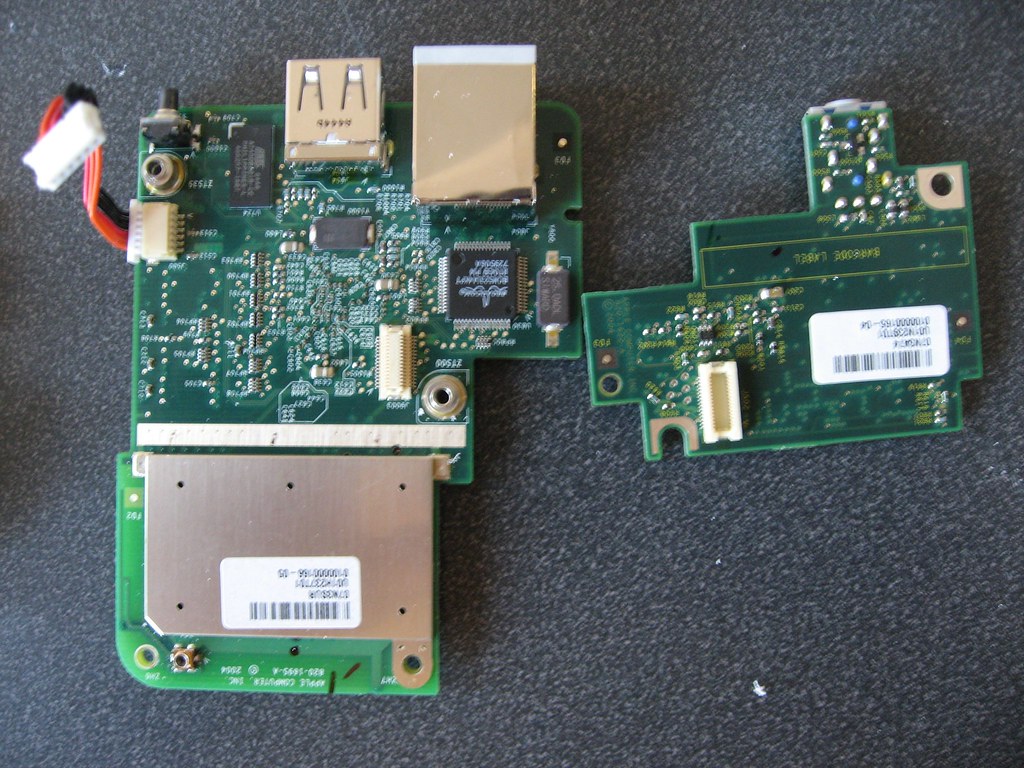
<p>The motherboard is actually made out of two boards. The larger board holds all the RF and computing stuff, and the smaller daughterboard holds the audio interface circuit. Here's a pic of the two separated:</p>
<p>
<a href="http://farm4.static.flickr.com/3570/3386315232_a059ce2b97_b.jpg"><img title="two boards" src="/assets/images/old_posts/3386315232_a059ce2b97_m.jpg" alt="Board and Daughterboard" width="240" height="180" /></a>
</p>
<p>Here's the back side of the motherboard:</p>
<p>
<a href="http://farm4.static.flickr.com/3616/3386315846_6992a3f299_b.jpg"><img title="Backsies" src="/assets/images/old_posts/3386315846_6992a3f299_m.jpg" alt="Back of the motherboard" width="240" height="180" /></a>
</p>
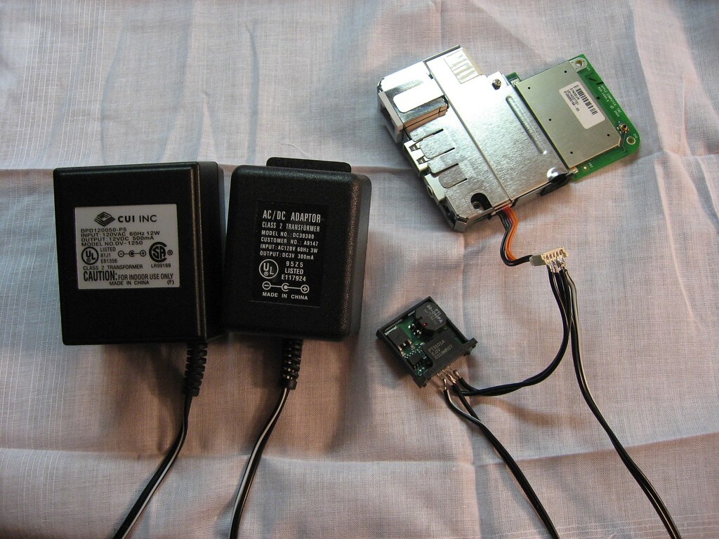
<p>Next, I sat down to try to figure out what was wrong with the airport express. I tossed a volt-meter on the power supply outputs and plugged it in, and it turns out the power supply was shot. Neither the 5V or 3.3V outputs were pumping out any juice. I briefly considered trying to troubleshoot the supply, but I decided it was easier jut to chuck it  and throw some wall-warts on the inputs. I had a 3.3V wall-wart, but no 5V supply, so I used the 3.3V supply and a 12V supply running through a <a href="http://www.datasheetcatalog.com/datasheets_pdf/P/T/5/1/PT5101A.shtml" target="_blank">TI PT5101A</a> 5V, 1A switching power supply:</p>
<p>
<a href="http://farm4.static.flickr.com/3609/3386313254_0e902736cc_b.jpg"><img title="wart it up" src="/assets/images/old_posts/3386313254_0e902736cc_m.jpg" alt="Complete with warts" width="240" height="180" /></a>
</p>
<p>Unfortunately, the 3.3V and 12V wall warts I had sitting around were only 300mA and 500mA supplies, whereas the Airport Express's original power supply was spec'd at 1.21A and 0.7A for each voltage. I was hoping that the Airport wouldn't require that much power to operate, but it turns out that it does. When I plugged the power supplies in, the green LED briefly lit up and slowly faded out. I'm going to try to hunt down some more powerful supplies and try again.</p>]]></content><author><name>Robert Ussery</name></author><category term="airport express" /><category term="hack" /><category term="power supply" /><category term="repair" /><category term="teardown" /><summary type="html"><![CDATA[I bought an Apple Airport Express off Craigslist a couple months ago so I can send music to my living room stereo via Airtunes. The little bugger quit working about a month in though, so I tossed it in a drawer to be put on Ebay for scrap or otherwise dealt with. As is wont to happen this semester, however, one day recently I got bored and went hunting around my room for things to do. I ran across the Airport Express and started wondering what was wrong with it. Here's the story of the teardown and my attempts at repairing it:]]></summary></entry></feed>