
CAN Bus Bridge
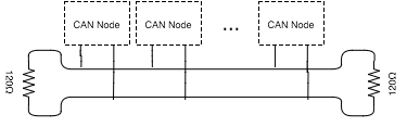
This project grew out of a problem we were running into at Airware. The physical layout of some of the aircraft we were putting our autopilot hardware onto made it difficult to properly terminate our CAN buses at each end. In a normal CAN bus, there all of the nodes are connected on a single bus, which is terminated by a 120Ω resistor at each end.
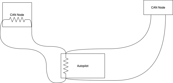
The autopilot we had designed had onboard termination for one end of the CAN bus, and then the other end would be terminated at one of the nodes on the bus. This made it difficult to terminate the bus correctly if the autopilot was not physically located at one end of the bus:
While the buses were generally small enough that we could get away with sub-optimal termination (like putting a single 60Ω termination in the middle of the bus), I thought it would be interesting to design a board to bridge two segments of a CAN bus, allowing each segment to be terminated properly.
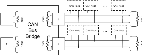
That’s where this project comes in. This board allows up to four separate CAN buses to be connected together and individually terminated, while sharing data between the buses. This enables a quasi-star topology CAN bus, with correct 60Ω impedance on each bus. Each of the four connectors can connect to a different CAN bus. The CAN bridge terminates each connected bus and bridges it to the other buses that are connected. It also bridges 5V power between all of the connectors, and powers itself off the 5V bus.
This diagram shows how this would be wired in a system:
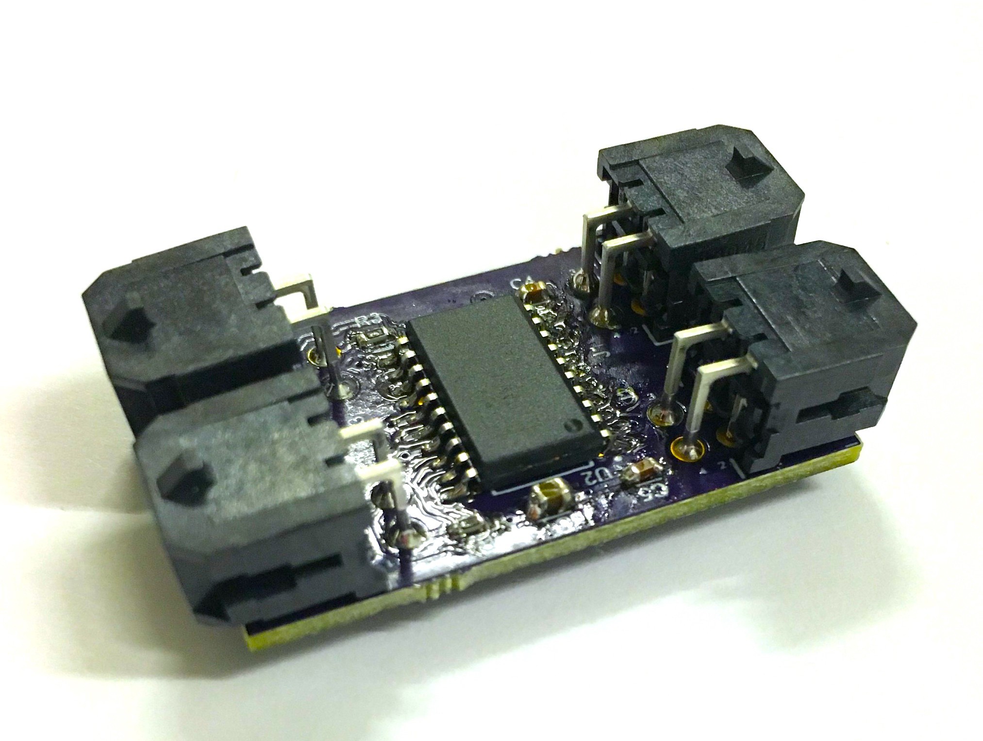
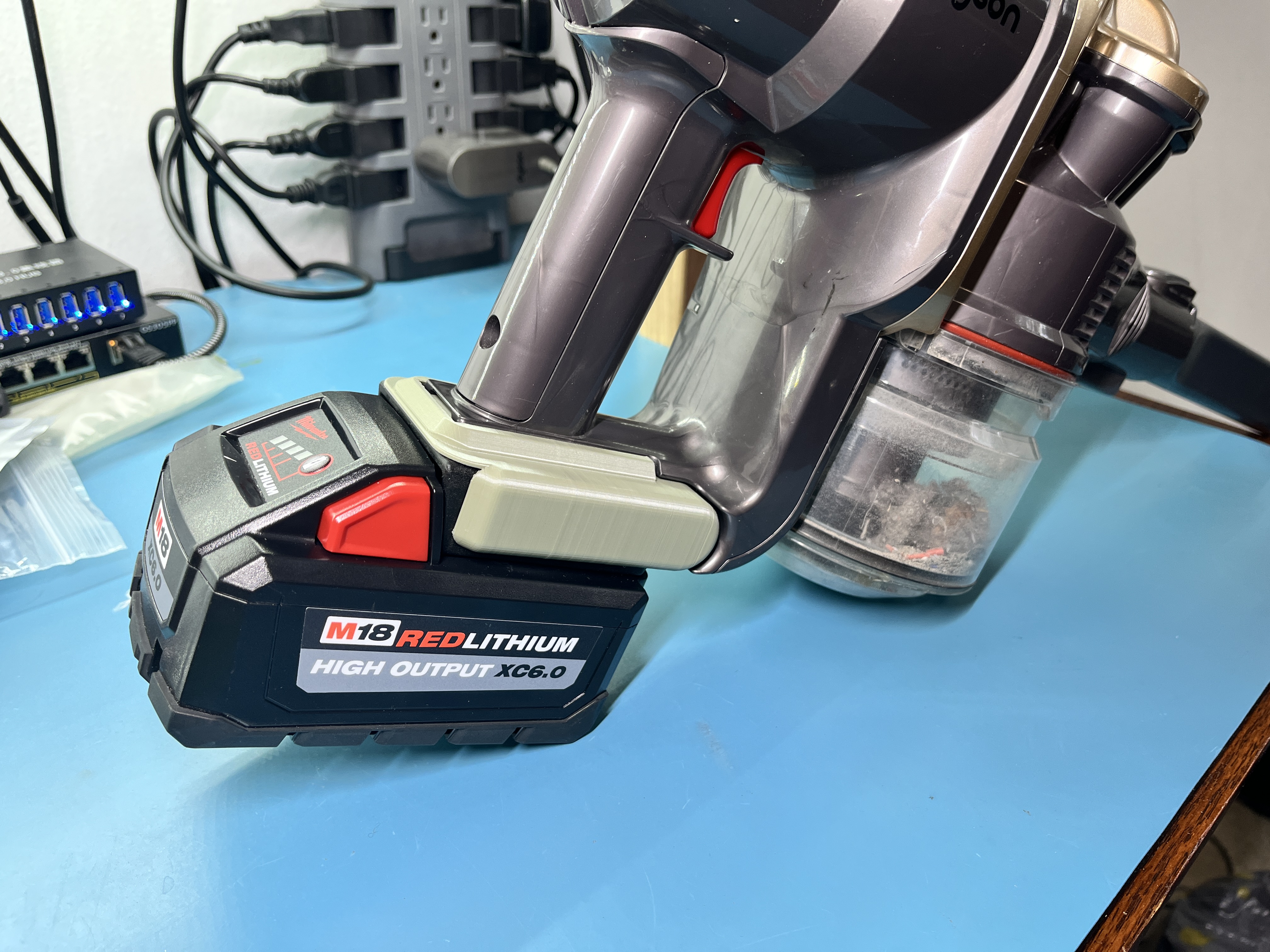
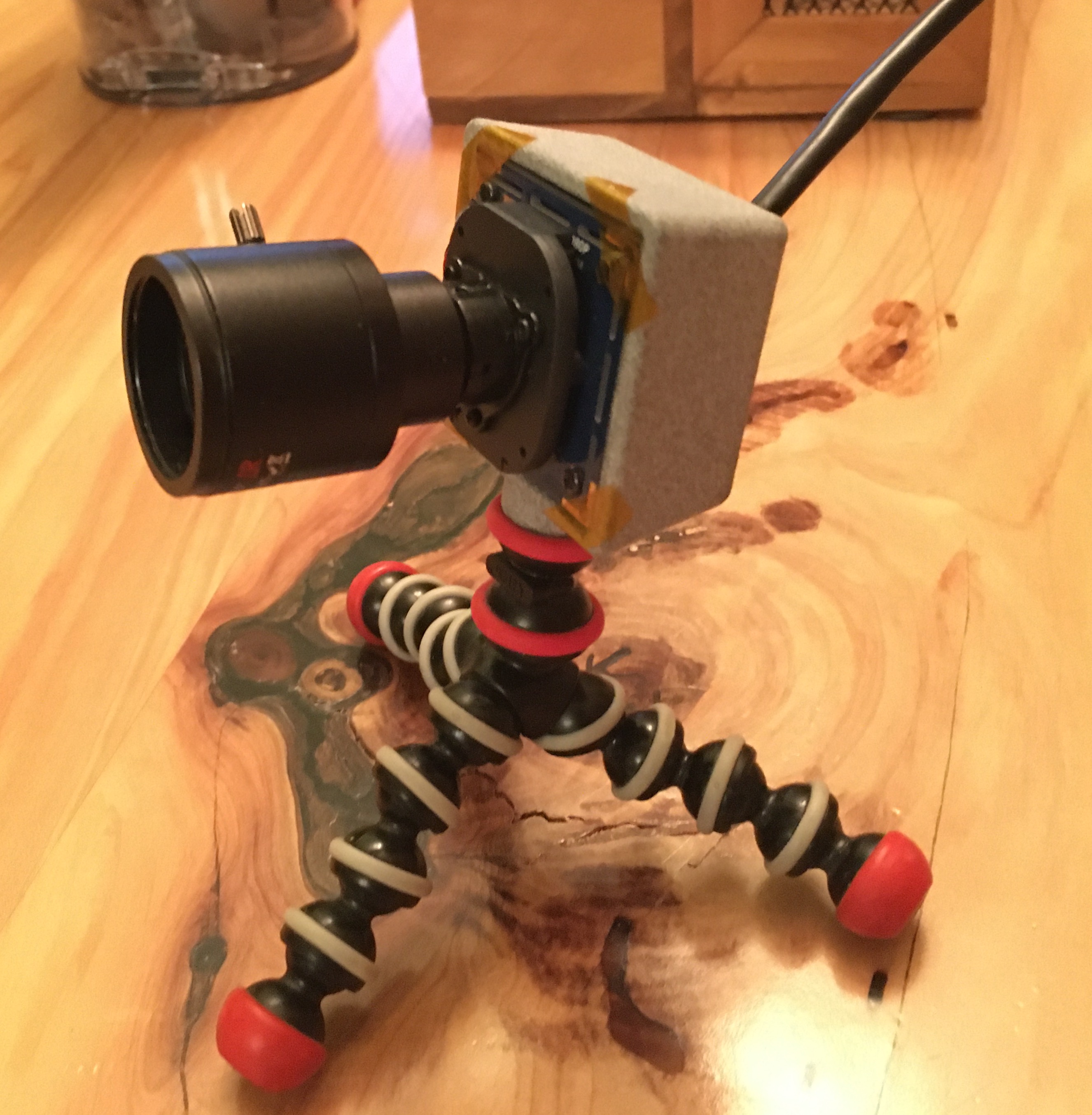
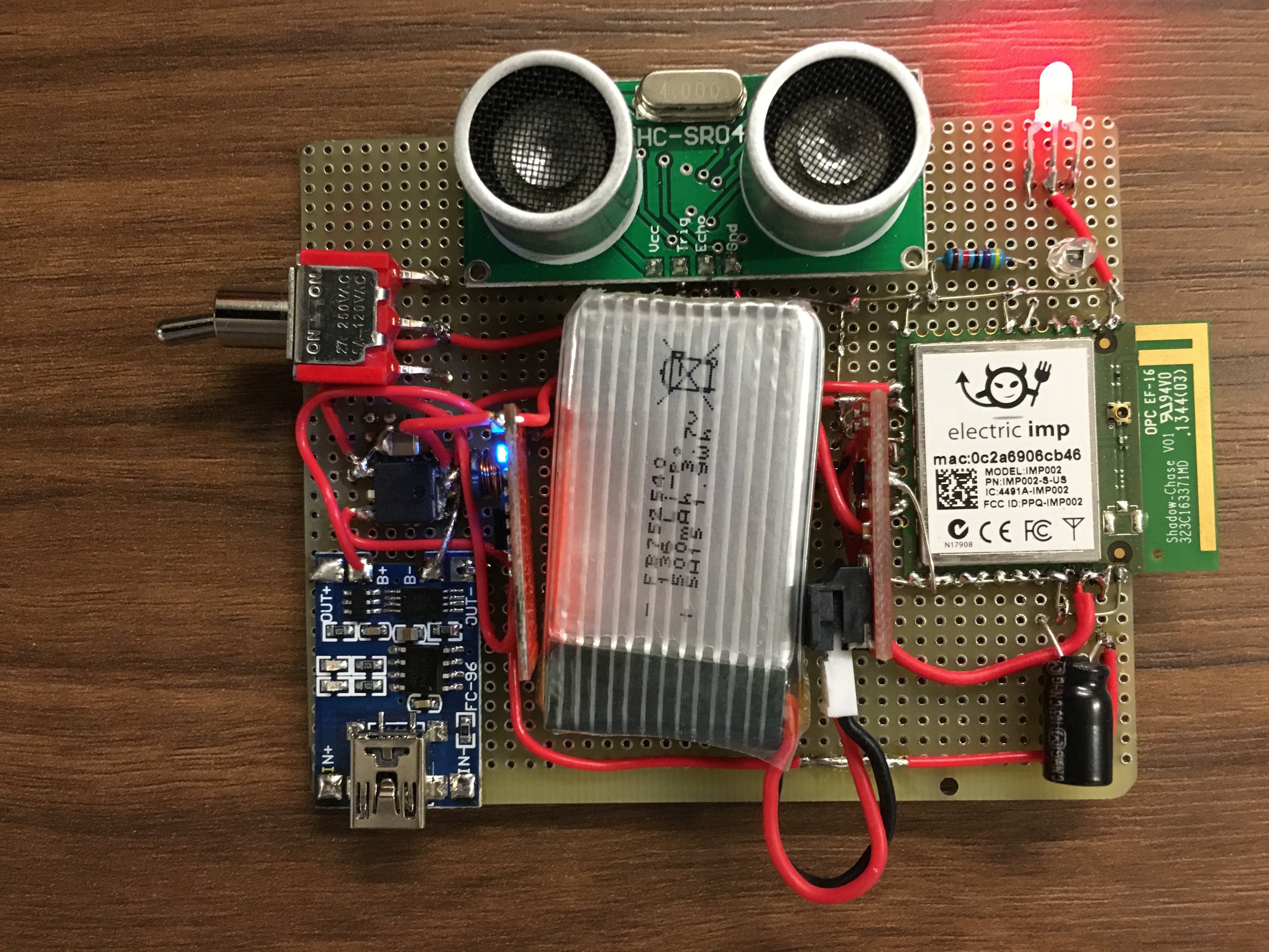
And here’s the finished hardware:
Full details here: https://github.com/russery/can_bridge
You can also follow this project on Hackaday.io: https://hackaday.io/project/8490-can-bridge
Leave a comment