HP Scanjet 4470 Teardown with Pictures
I'm in the process of cleaning out my room in preparation for my move to California at the end of this semester, so I decided to dig into my box of old electronic crap that I've been hauling around for a few years. In doing so, I ran across my trusty old Hewlett Packard Scanjet 4470 scanner that I've had since middle school. It hasn't worked for a couple of years due to a bum power supply, but I managed to scrounge up another 12 volt supply and turn it on. It turns out that all these years of hauling it around have caught up with it, and it doesn't scan very well anymore. I tried several scans with it, and they all came out with rainbow lines across them:

After reading a few forum posts, I came to the conclusion that the CFL tube used to front-light the media being scanned is on the fritz. Couple this with the fact that HP doesn't have any drivers that will work with Leopard, and I decided it was time to retire the old scanner to the dumpster. Being a EE, I couldn't resist tearing it apart first to see its guts, so I thought I'd share the results of that with you, and thus begins...
The Teardown:
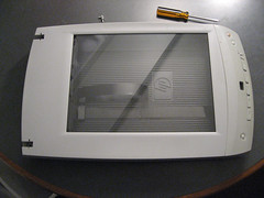
The scanner is opened by removing two screws on the front, and opening the case like a giant clamshell:
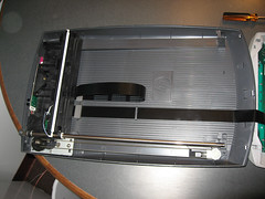
On the inside, you can now see the image sensor carriage, the belt drive that moves it, the main PCB, the ribbon cables connecting the carriage and front panel, and at the far right the PCB that holds the switches and LCD for the front panel. I was somewhat surprised to find that the sensor carriage rides on a single rail, with the opposite side of the carriage riding on a wheel which goes down an open track. I guess the bushings that ride on the rail are stiff enough to prevent any torsion of the carriage in the plane of the scanner, and rotation of the carriage out of the plane is prevented just by gravity. I guess HP saved a few bucks by building it with only one rail.
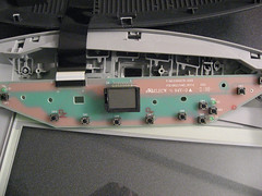
Here is a closeup of the PCB that holds all the user interface switches and the LCD:
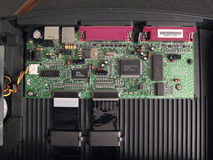
The LCD is sitting on a little rubber "table" that cushions it and keeps it pressed against the viewing window. Following is a closeup of the main PCB. There's not really much to it... a stepper motor driver chip, an HP Scanner ASIC, what apears to be a RAM buffer, and a whole mess of discretes. Simple, but then again I guess most of the heavy lifting is done by the PC software.
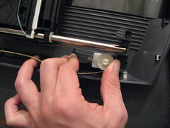
Removing the sensor carriage was very simple, as it wasn't even bolted in. Removal consisted of slipping the drive belt off the far pulley
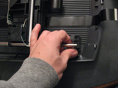
... followed by simply lifting out the carriage rail
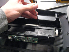
Inside the sensor carriage, we find all kinds of optical goodies, including front surface mirrors, a lens, and the CCD sensor itself. The mirrors were just held on with little metal clips which could be popped off with a flathead screwdriver:
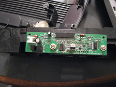
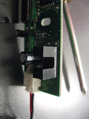
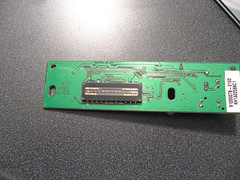
After popping out the three mirrors, I removed the sensor PCB which carries the image sensor itself, a bunch of discretes, and an photointerrupter (the black tallish doo-dad) to let the carriage know when it has reached its home position:
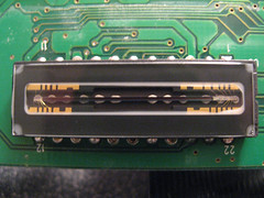
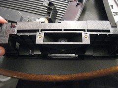
Inspecting the CCD closely, it appears that it is only three pixels tall or so, with a line of pixels for red, green, and blue. Here is a view of where the sensor PCB mounts, looking down into the lens that focuses the scanned image onto the CCD:
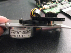
That's about all there was to the image carriage. Next, I removed the drive motor. It was held in with a single screw, as shown below. I must say, HP made it really easy to pull this puppy apart.
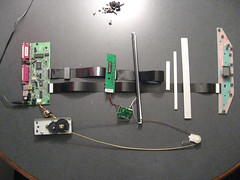
Here are all the electronic goodies laid out more or less how they fit into the scanner:
One thing I didn't get a picture of before was the CFL and its inverter, which can be seen wired up to the CCD circuit board. Also shown in this picture are all three of the mirrors that convey the scanned image to the CDD.
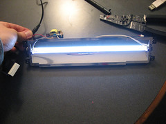
This particular scanner model came with an attachment to backlight negatives and slides so they can be scanned. I didn't get any pictures of its teardown, but it was pretty simple on the inside, with just a CFL tube and inverter mounted into a reflector. I decided to see how bright the two CFLs (this one, and the one from the scanner itself) would be when wired up together:
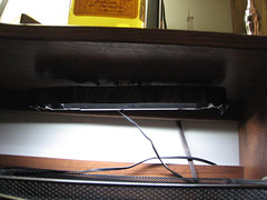
They weren't exactly blindingly bright, but certainly bright enough to do something with. The obvious application was a little CFL desk-lamp, which I hacked together with the 12V wall wart, the two CFL's and inverters, and the reflector. I added a little ribbon cable from the scanner around the edge to pretty it up, taped it under my desk, and called it a desk lamp. It lights up my inbox nicely... dubiously useful, but kind of neat in a geeky sort of way:


Leave a comment